Wiring harness design in CATIA V5 - 3D modeling Week 5 & 6 Challenge
1. Creation of Harness A:
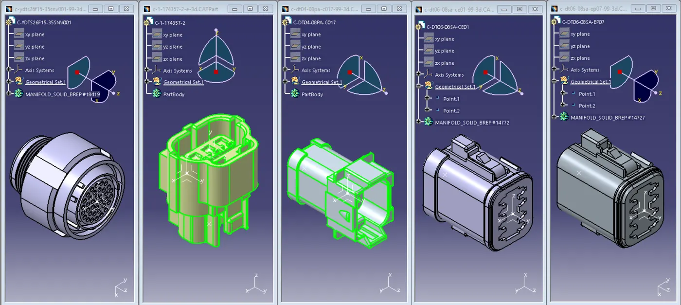
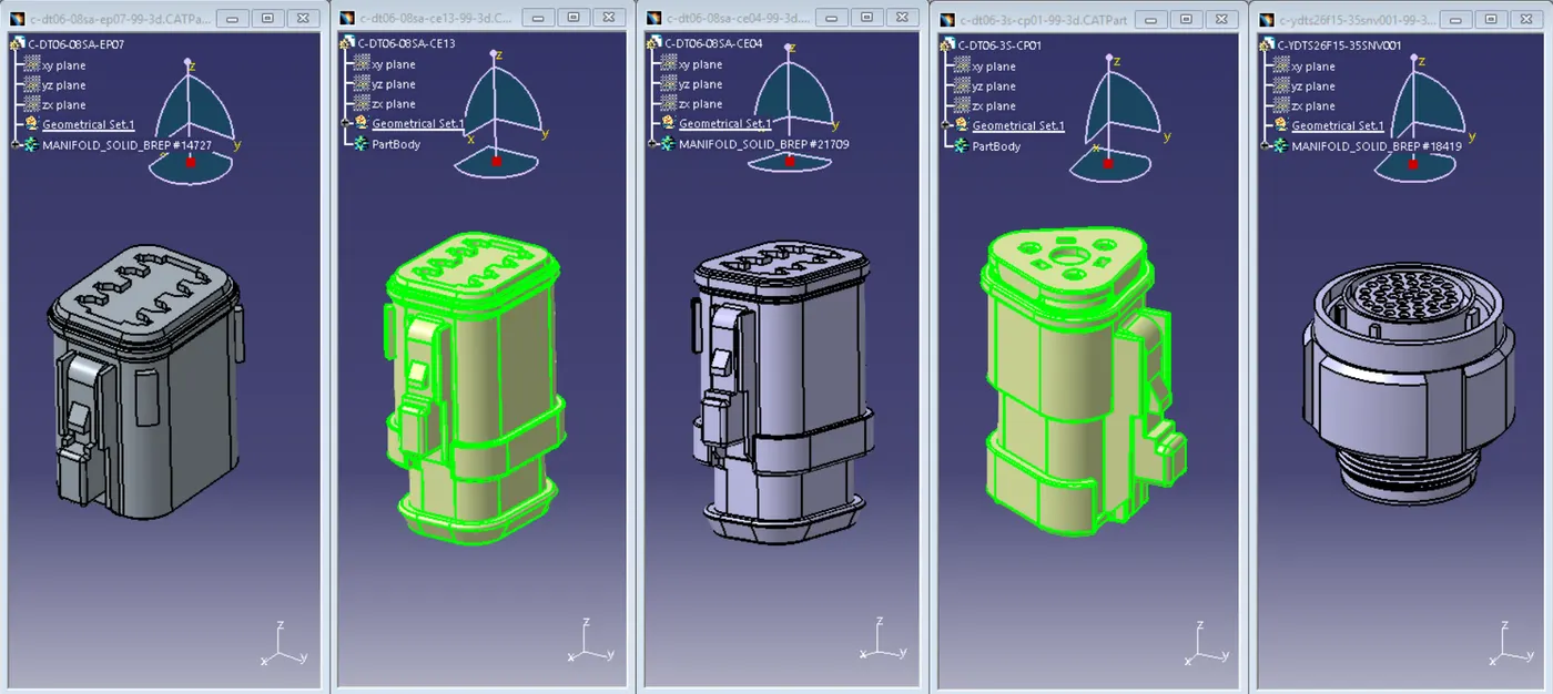
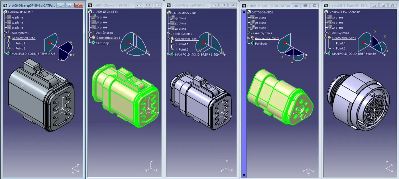
Step 1: Downloading and adding the required geometrical properties to the mechanical parts
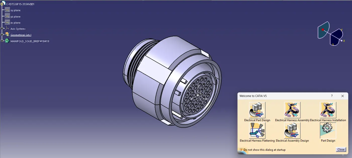
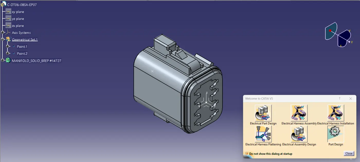
Go to Electrical part design workbench to proceed further
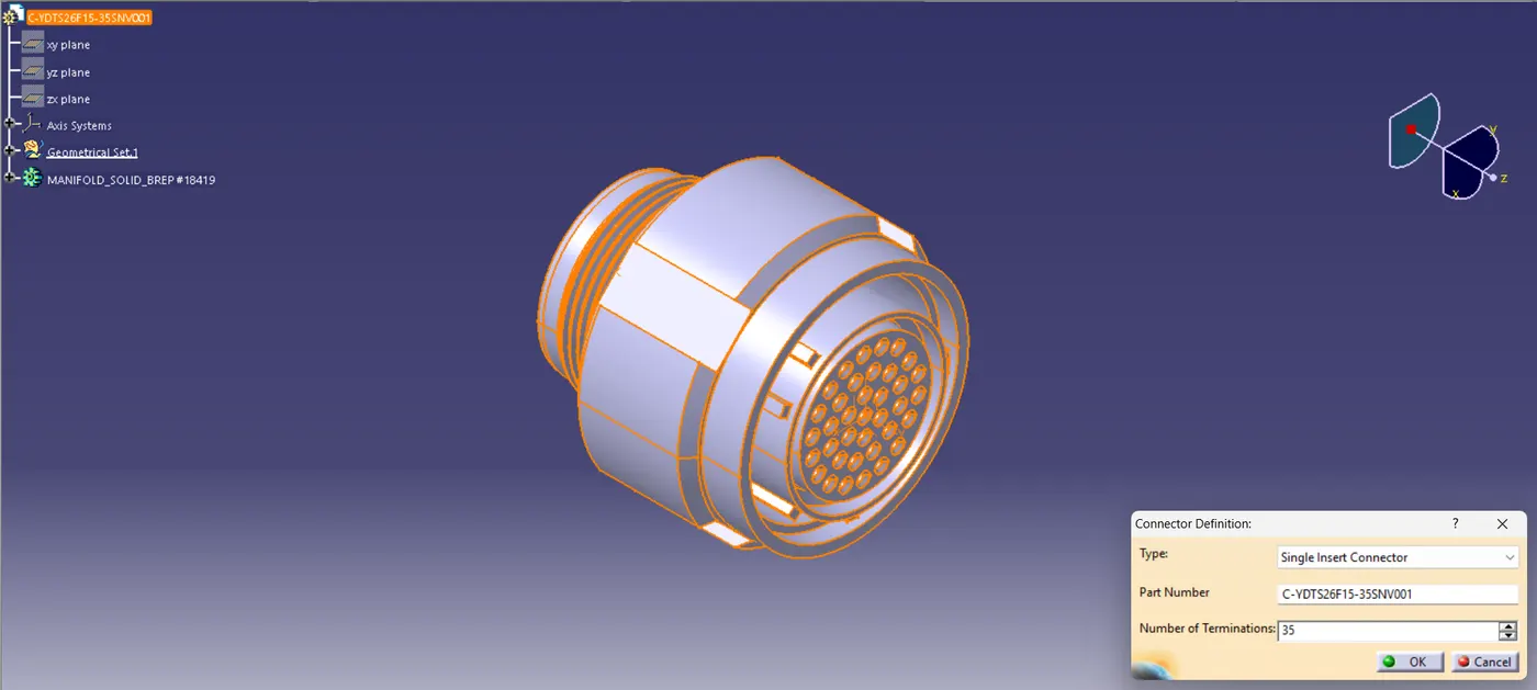
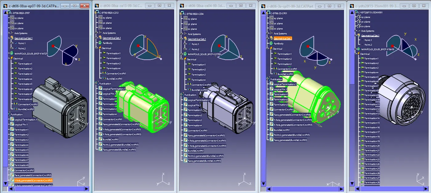
Step 2: Defining the mechanical component as a connector by specifying number of terminations
adding electrical properties to it such as connector connection point and bundle connection point to the connector
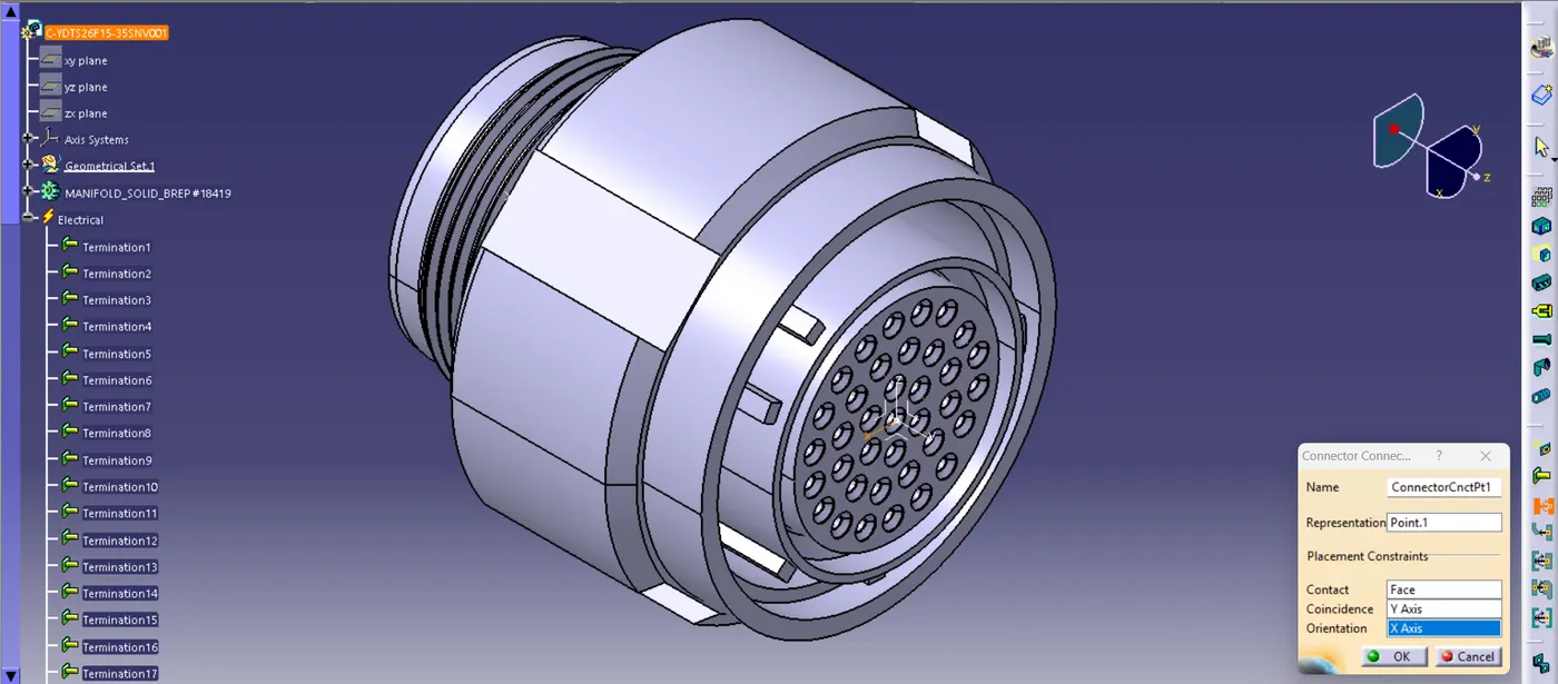
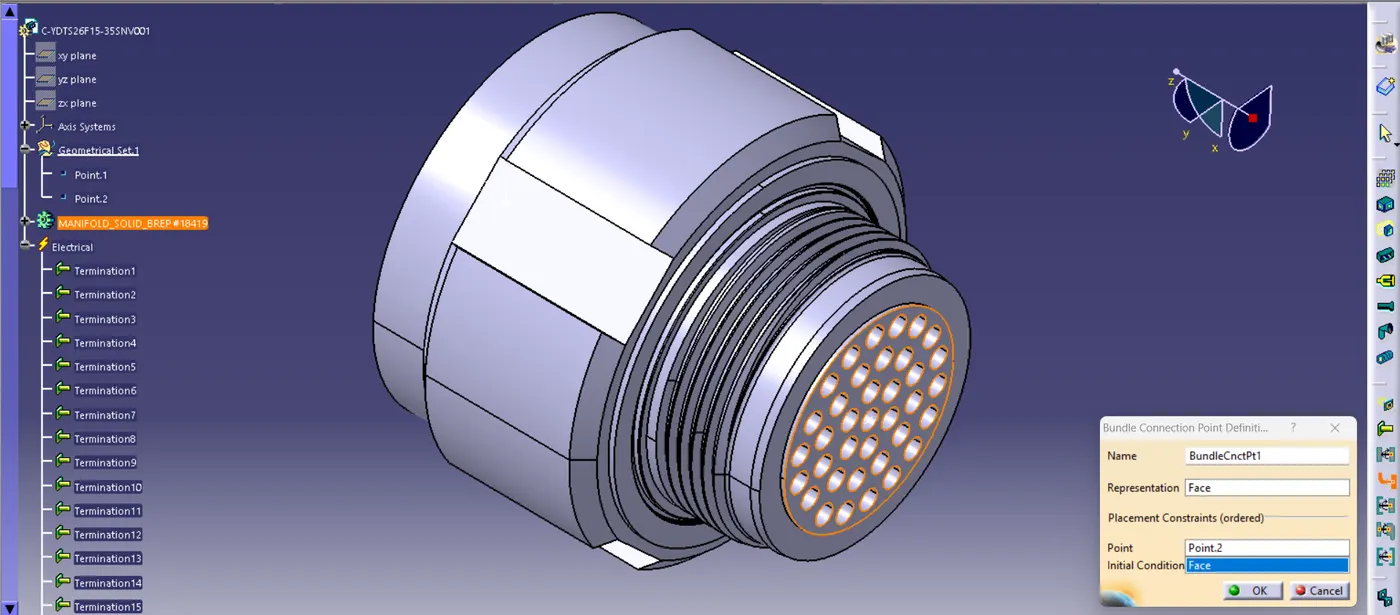
Similarly following the procedure to define all the connectors of Harness A
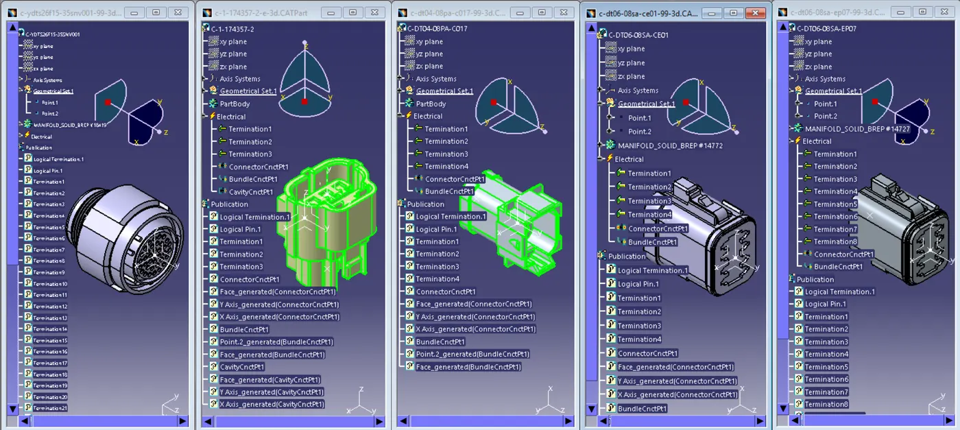
Step 3: Creation of Catalog and adding all the connectors to it under family for future use also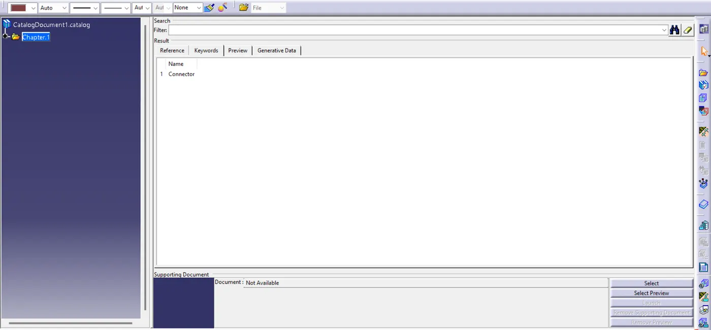
Step 4: Creating a new product file and after renaming it as Harness A adding connectors 6 to 10 and placing them desired location
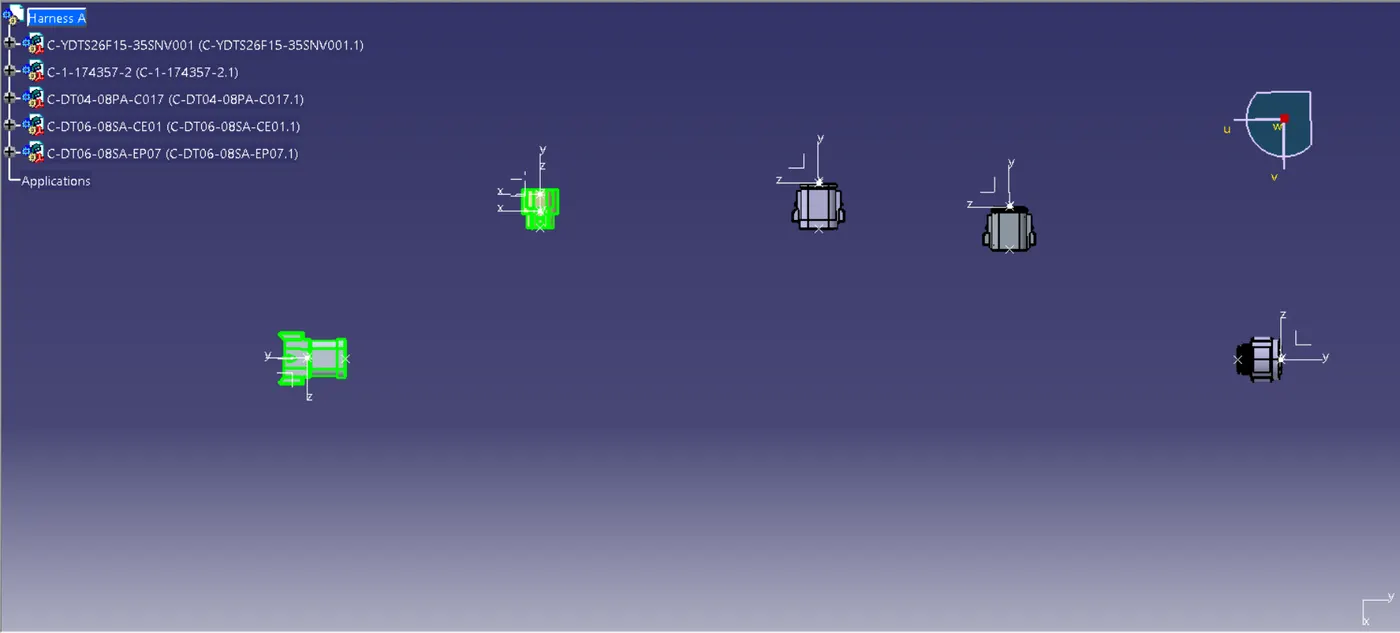
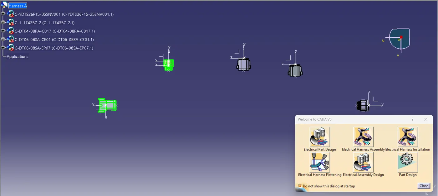
Go to >> Electrical Harness assembly workbench to proceed further
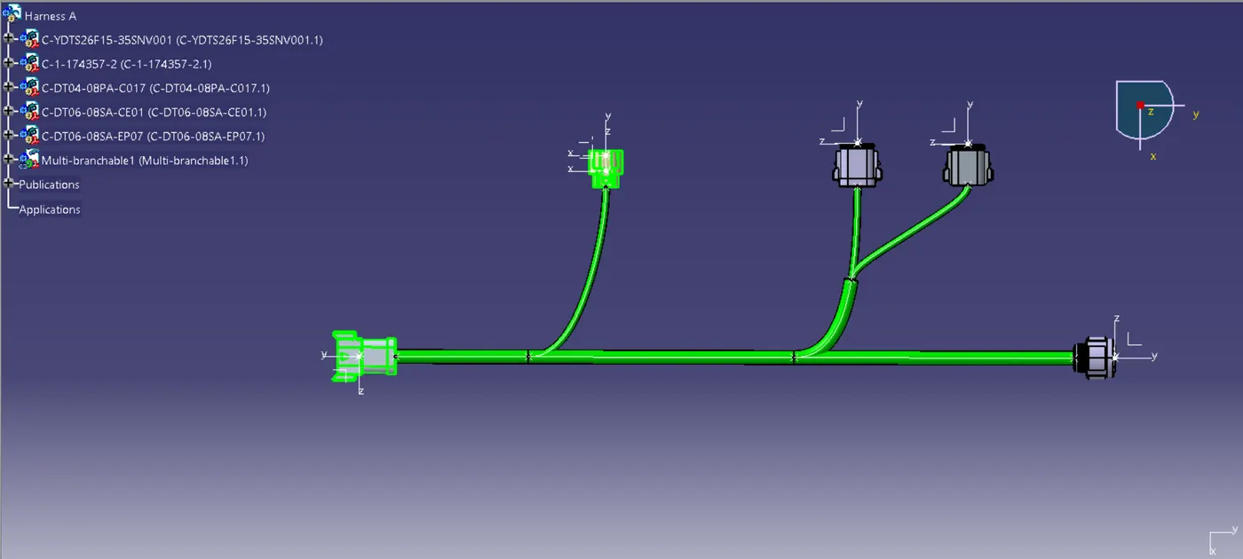
Step 5: Converting mechanical assembly to electrical assembly by using multi blanchable command and creating multiple branches to connect connectors
2. Creation of Harness B:
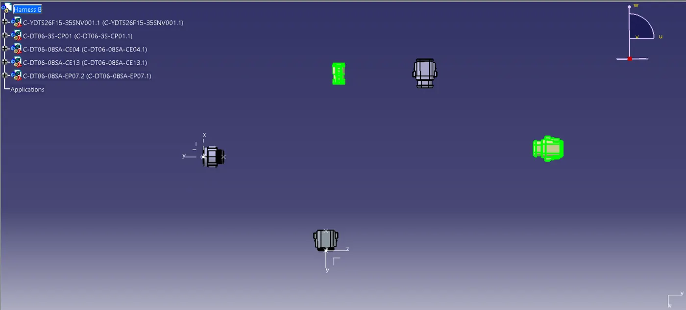
Following the above-mentioned steps let's create harness assembly B also from definition of electrical part & addition of electrical parts to catalog up to creation of harness B in harness assembly workbench the procedure is completely similar
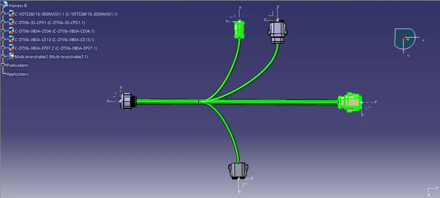
3. Creation of Electrical Harness assembly (Harness A + Harness B):
Create a new product file and renamed it as Electrical Harnes Assembly and adding the Harness A & Harness B product file to it
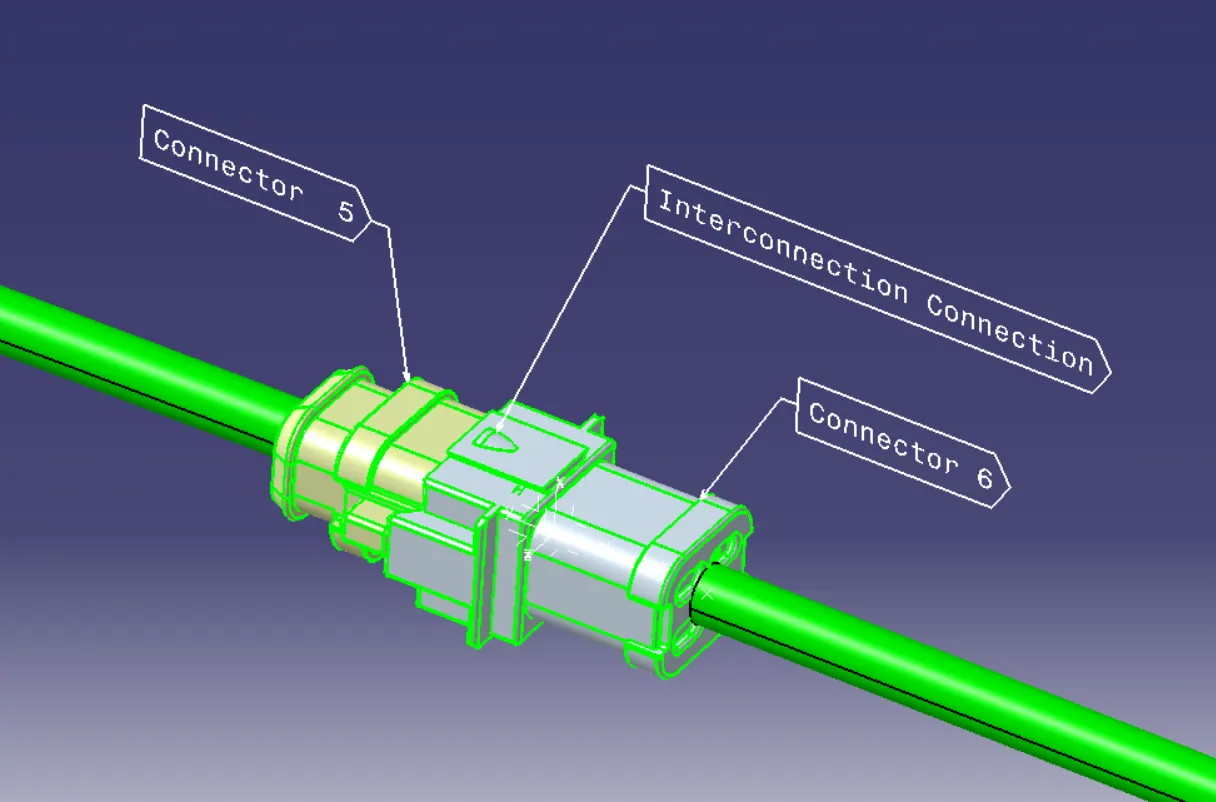
such that interconnection connection of Harness A & Harness B would be created.
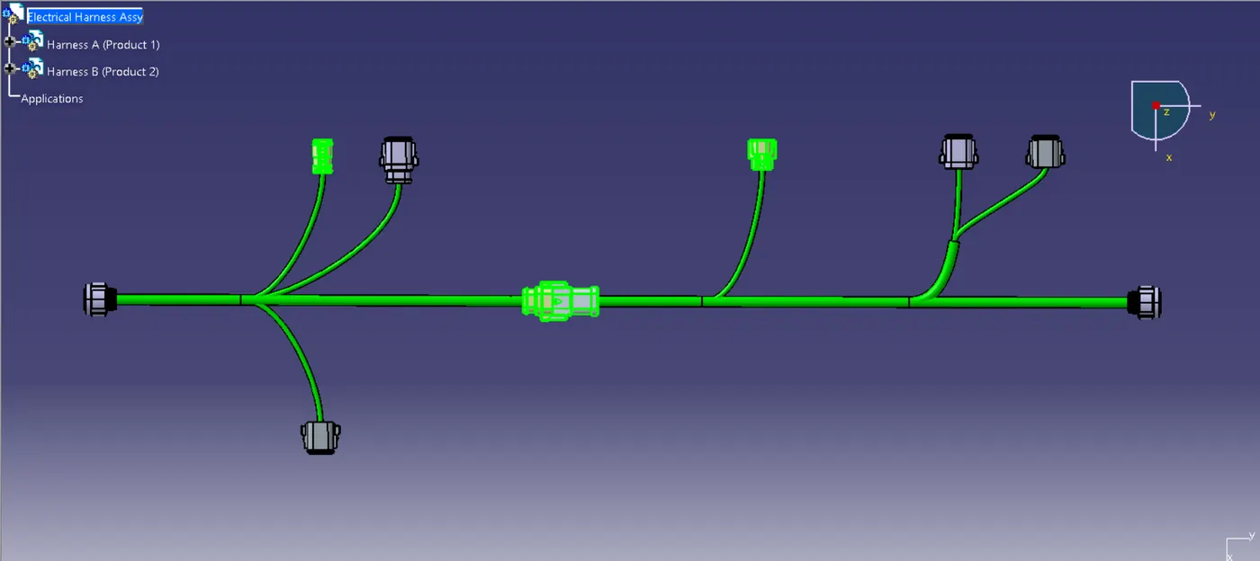
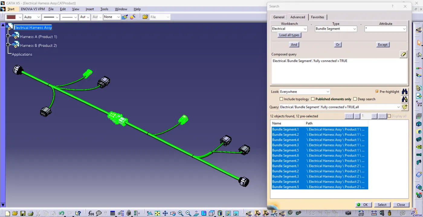
In the next step we need to check the continuity of the bundle segment whether they are fully connected or not (if not, error will appear) as shown in the image all the bundle segments are fully connected to each other so we can proceed further
Now we need to add the Annotation for different connectors as shown below
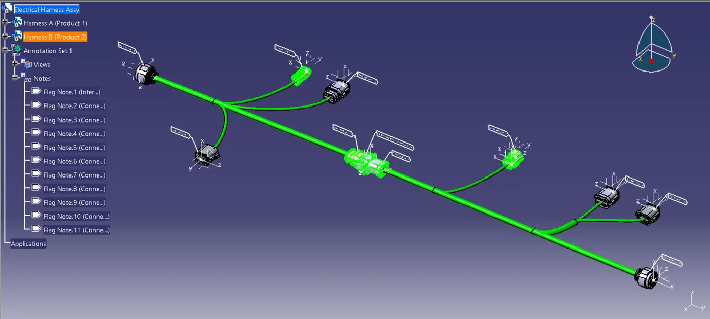
Interconnection connection,