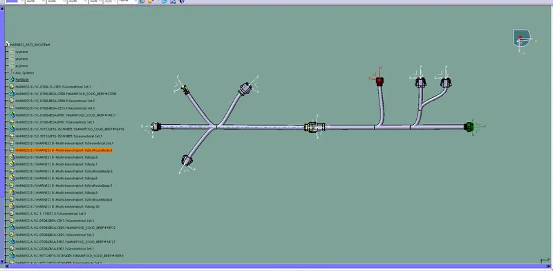
Wiring harness design in CATIA V5 - 3D modeling Week 5 & 6 Challenge
AIM:
- To create the assembly wiring harness as per given route mapping
- Check the bundle continuity
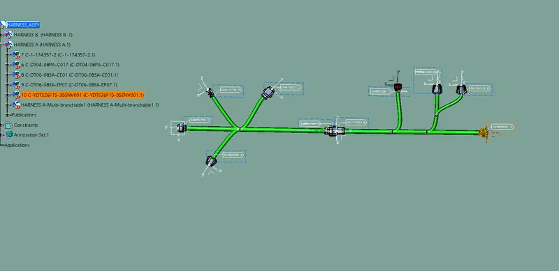
- Add annotation to all connectors
- Check for the bundle warning
- Generate CAT.part off harness assembly and convert is in .igs format
GIVEN:
ROUTING MAPPING
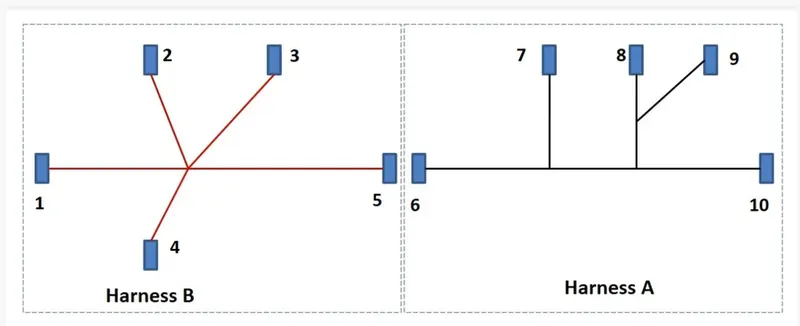
CREATING THE ASSEMBLY WIRING HARNESS
STEP 1:
Download all CAD file from given link
STEP 2:
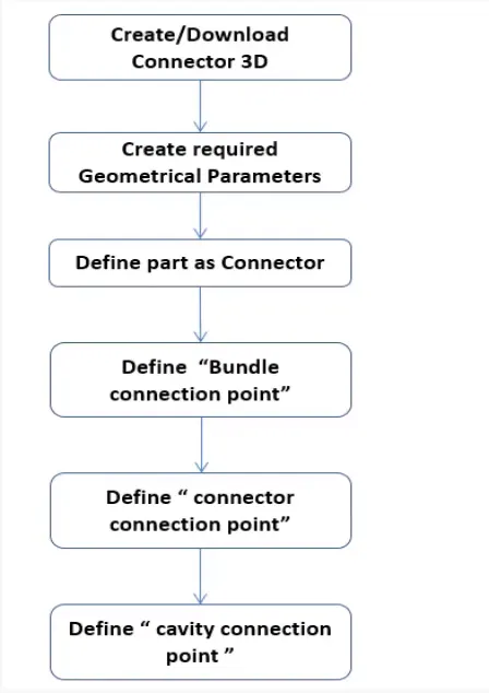
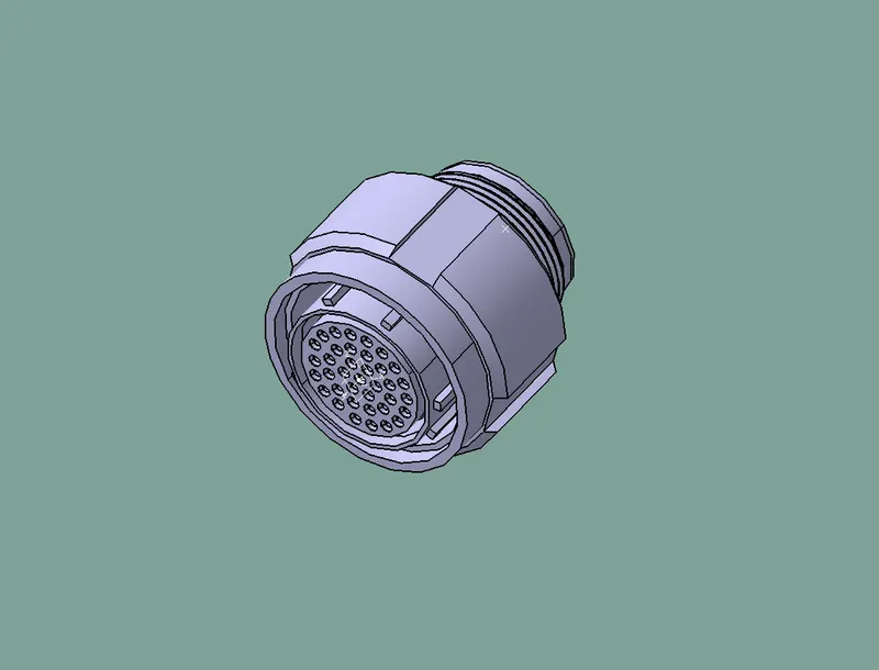
Define all connector as Electrical part by using Electrical Part design workbench
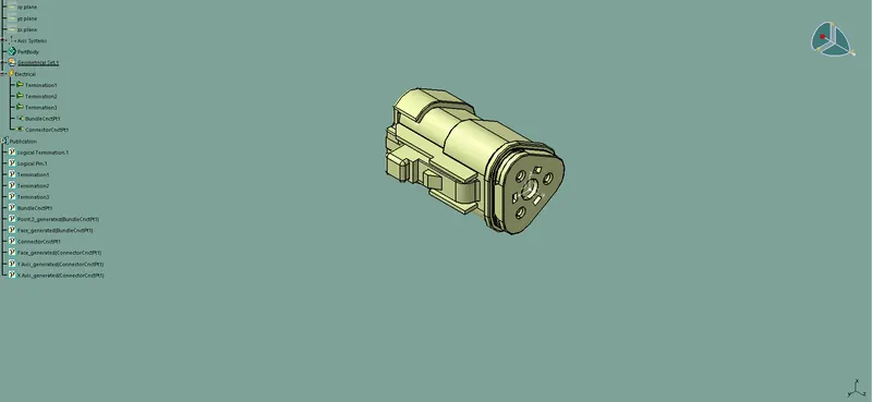
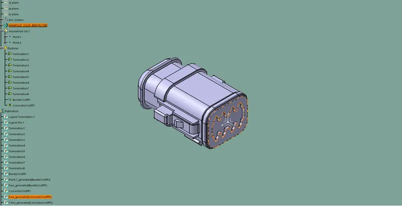
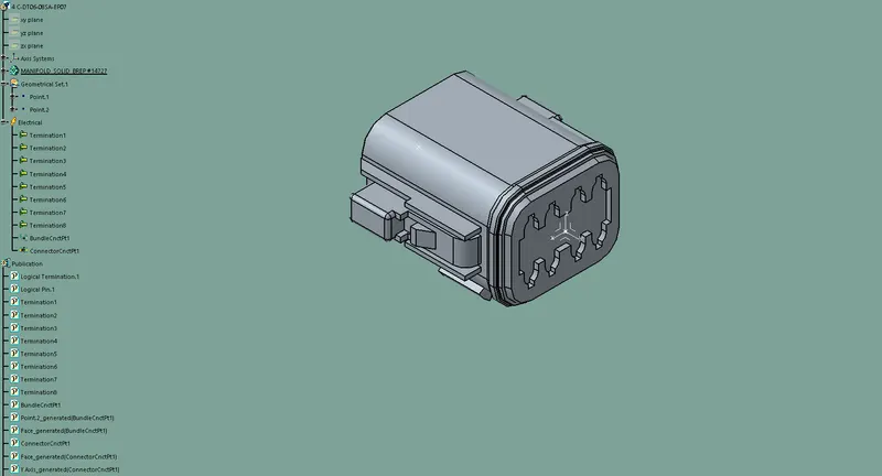
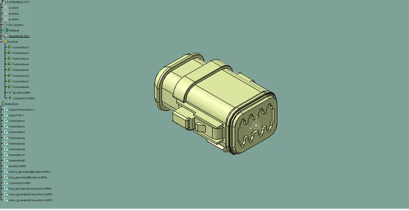
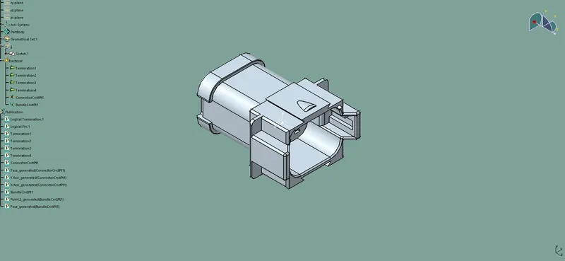
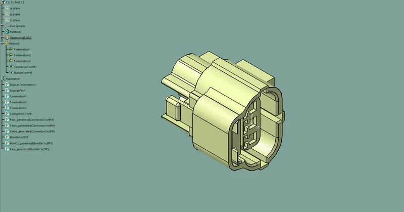
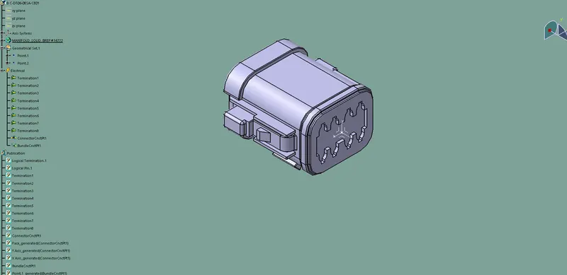
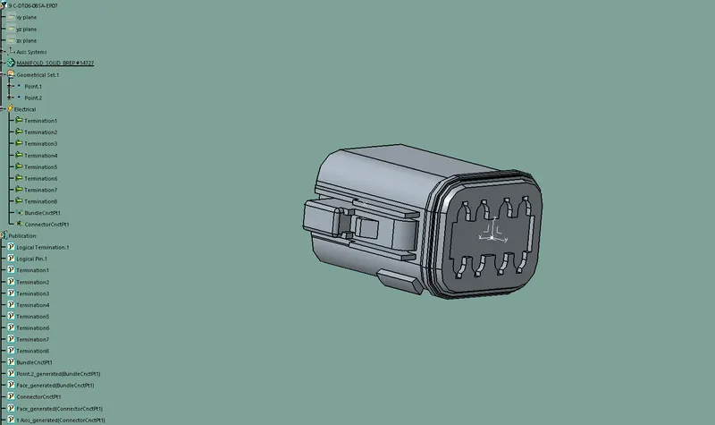
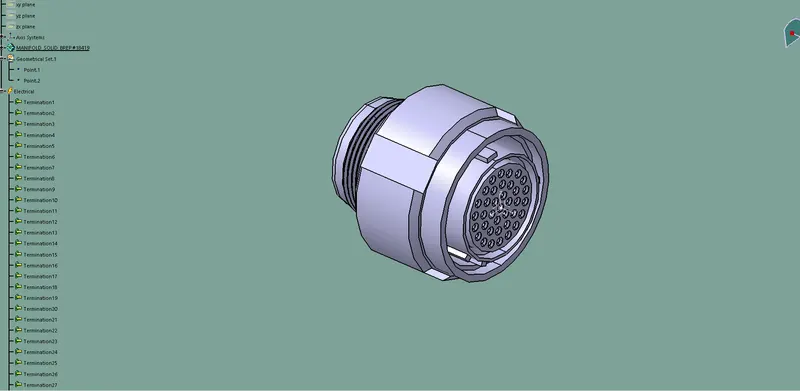
STEP 3:
Add connector to the catalog
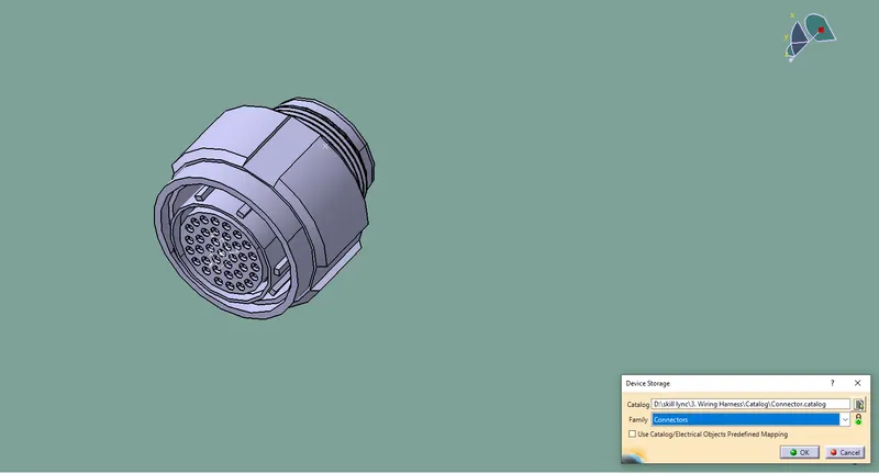
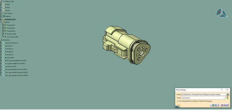
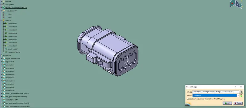
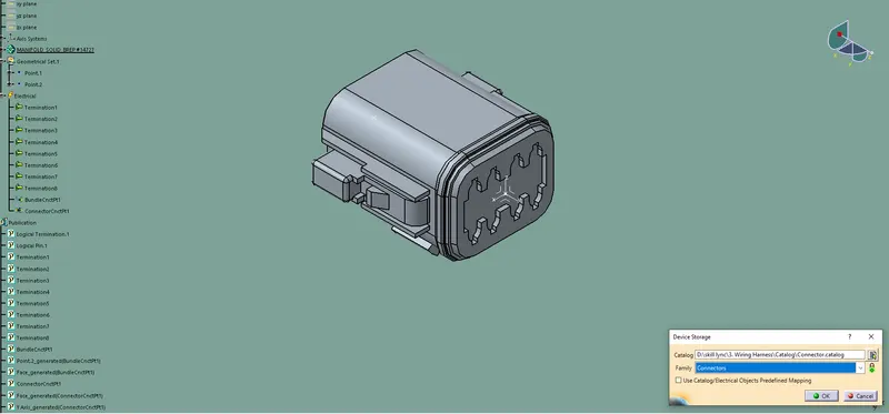
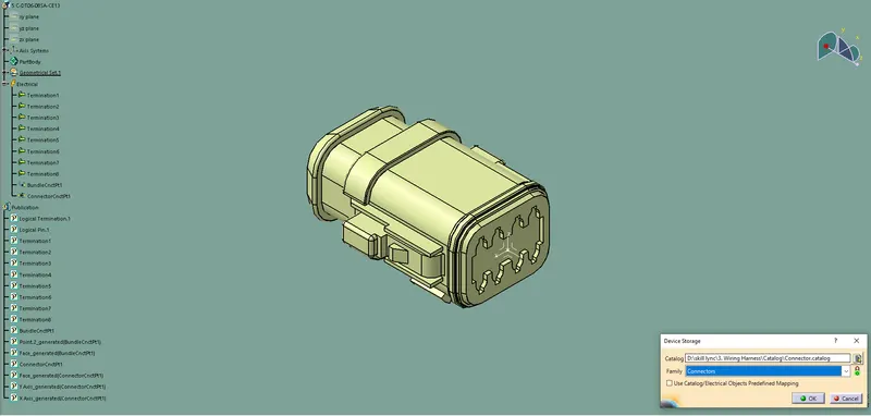
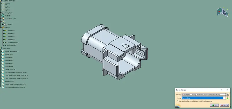
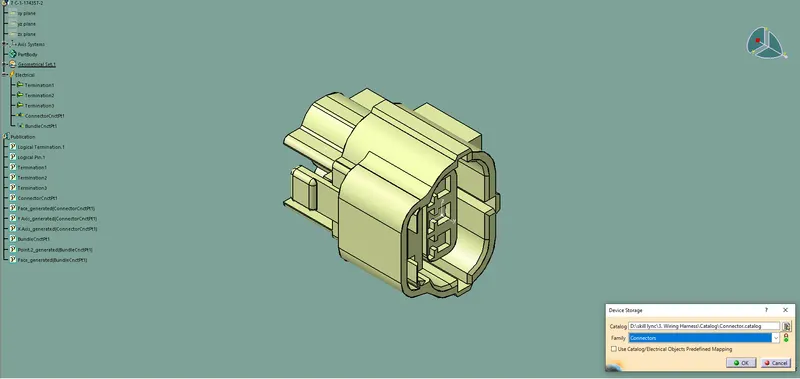
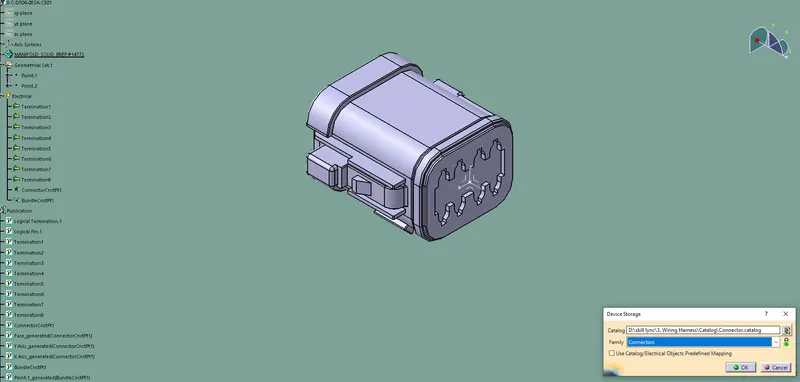
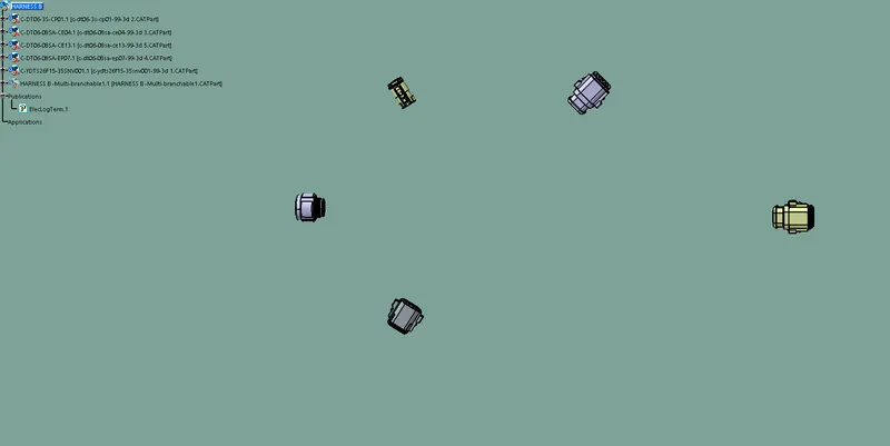
STEP 4 :
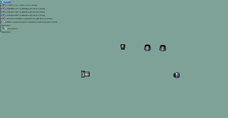
Arrange the connectors as per route map given
HARNESS B
HARNESS A
STEP 5
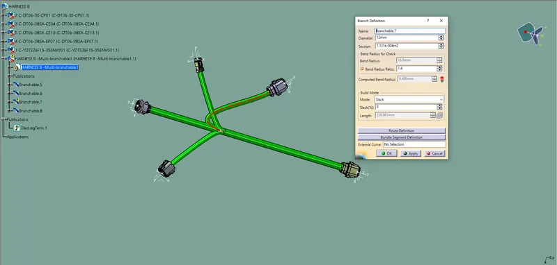
Create the multi-Branching to the connectors as shows in route map
HARNESS B
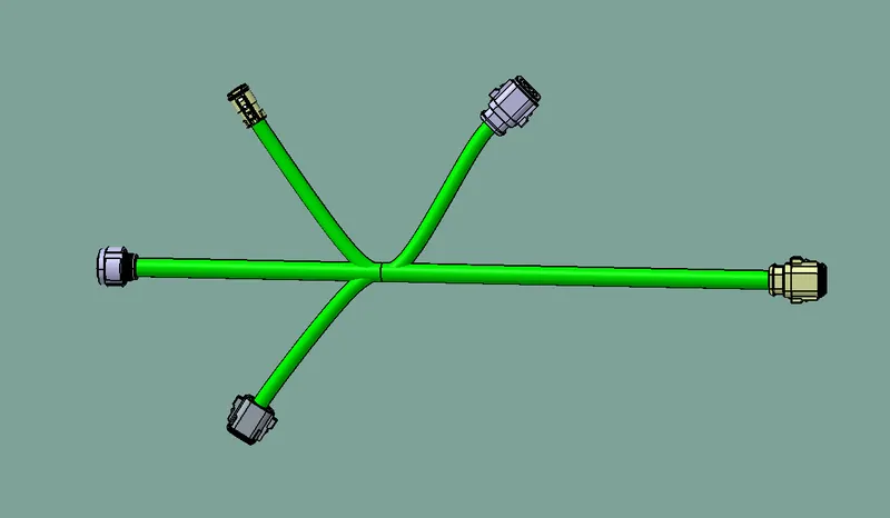
HARNESS A
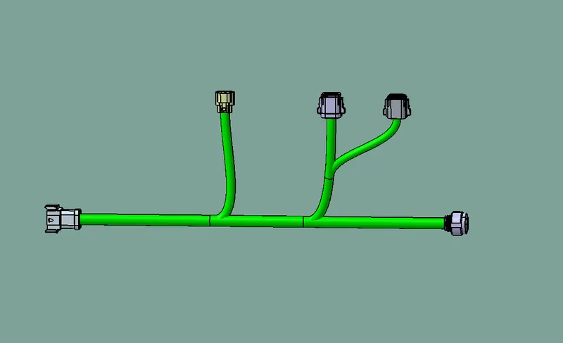
STEP 6 :
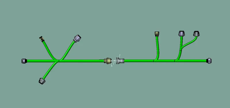
Interconnect the HARNESS B & HARNESS A
- Create new product and paste both Harness A & B on the new product
- Then Shift to Electrical Assenbly design workbench
- Click on Connect electrical device command then interconnect the connector 5&6
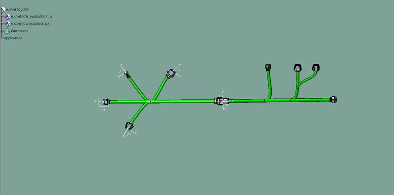
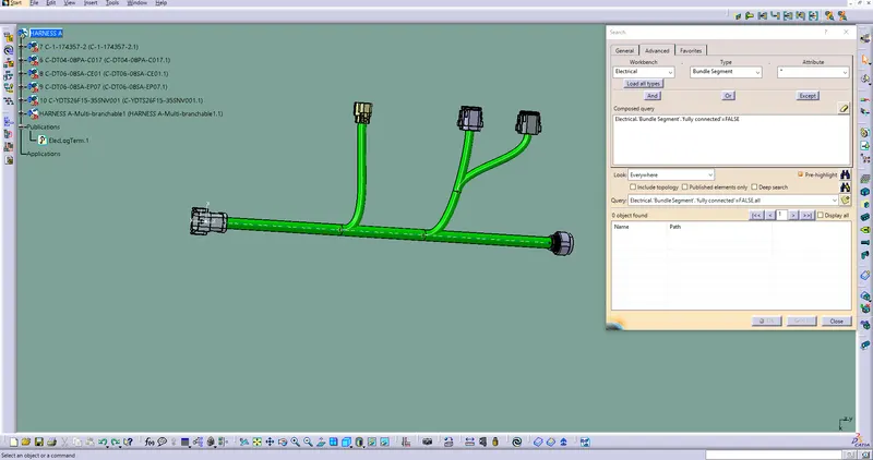
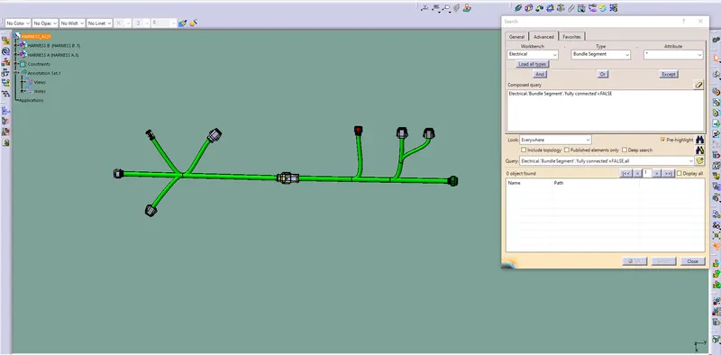
CHECK THE BUNDLE CONTINUITY
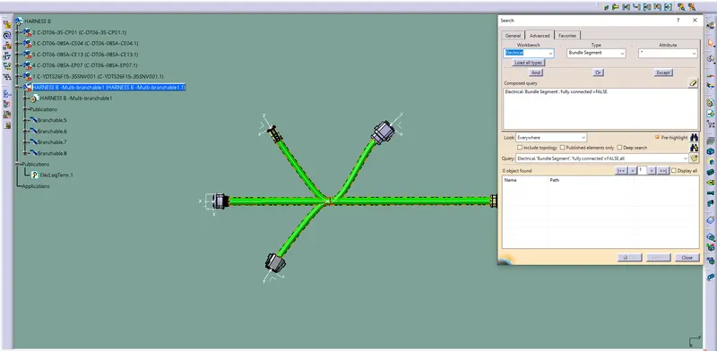
- For checking the bundle continuity go to EDIT >SEARCH
- Now a tab open then click advanced
- In that Workbench select Electrical ,Type select Bundle Segment,Attribute select Fully connected , THEN FALSE
- Now Click search IF there is no object found then its fully connected
HARNESS B
HARNESS A
HARNESS ASSY
CHECK FOR BUNDLE WARING
ADD ANNOTATION TO ALL CONNECTORS
GENERATE CAT.PART OF HARNESS ASSEMBLY AND CONVERT IS IN .IGS FORMAT