Wiring harness design in CATIA V5 - 3D modeling Week 5 & 6 Challenge
AIM:- To route the Harness layout in Eletrical workbench by using the connectors which taken as an inut
Objectives:
- To Check the Bundle Connectivity.
- Adding Annotations to connectors.
- check for bundle warning
- Generate CATPart and make STP or IGS File...
INPUT
We have to route the harness as shown in below Harness Layout.
the connector data is given we have to download from links provided.
CONNECTORS DATA
| CONNECTOR | DESCRIPTION |
| 1 | C-YDTS26F15-35SNV001 |
| 2 | C-DT06-3S-CP01 |
| 3 | C-DT06-08SA-CE04 |
| 4 | C-DT06-08SA-EP07 |
| 5 | C-DT06-08SA-CE13 |
| 6 | C-DT04-08PA-C017 |
| 7 | C-1-174357-2 |
| 8 | C-DT06-08SA-CE01 |
| 9 | C-DT06-08SA-EP07 |
| 10 | C-YDTS26F15-35SNV001 |
step 1
- seperate the igs files
- create catia part files
- segregate harness a and hareness b
- elecally define the connectors
- create connector connection point and bundle connection point
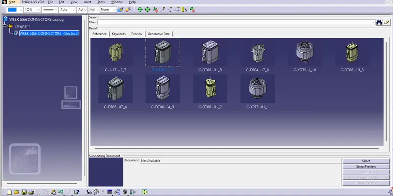
- create a catalog and strore the connectors in that catalog-ue
CATALOUGE CREATION
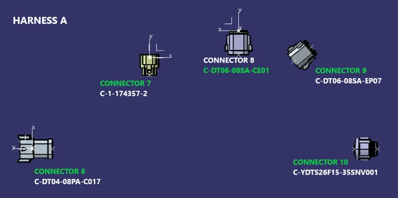
HARNESS A
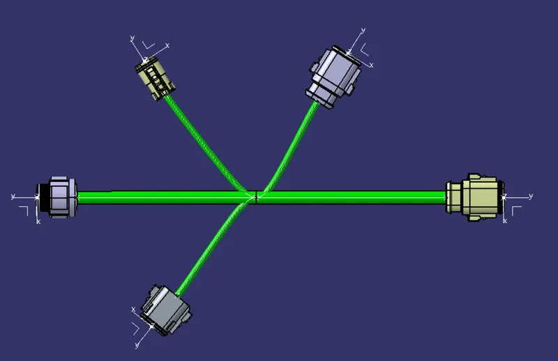
Connectors are placed according to the Layout given and bundles are connected between then
Bundle connection
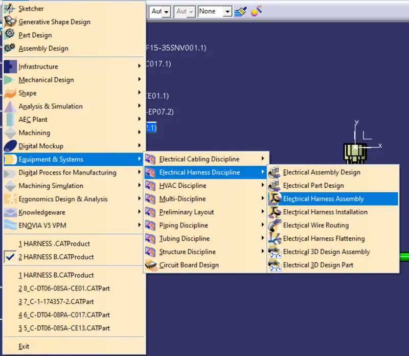
To created bundle connections we have to entre to Electrical Harness Assembly
as shown in the figure
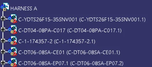
PRODUCT -----> GEOMETRICAL BUNDLE
Convert the Product into Geometrical bundle by clicking the product icon by selecting geometrical bundle attribute

After that product icon will be changed so its defined as electrical product
CONNECTING CONNECTORS
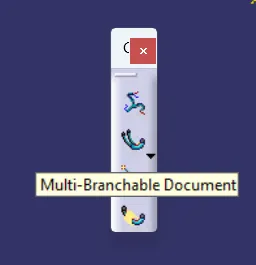
Select multi Branchable icon as shown
Branch Defination
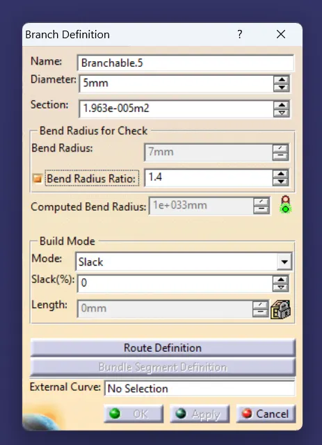
Entre the Bundle diameter bend radius slack if needed
after that Click Route Defination at the bottom
it will take you to other window where you need to give connector and tangent direction
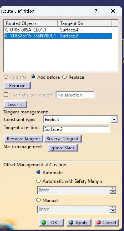
by following this we have to create the Bundle and connect the connectors as shown in below fiigure
HARNESS B
follow the same procedure as Harness A
Harness B should be created in another Product
Assemble Both HARNESS A AND HARNESS B
To assemble the harness first we need to import both Products in one separate Product and name it as Haness
Entre into Harness Assembly Design
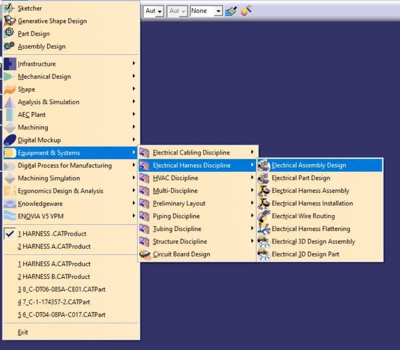
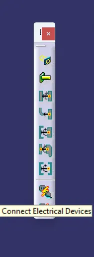
connect both Harness as shown using Connect command
Connect electrical Device
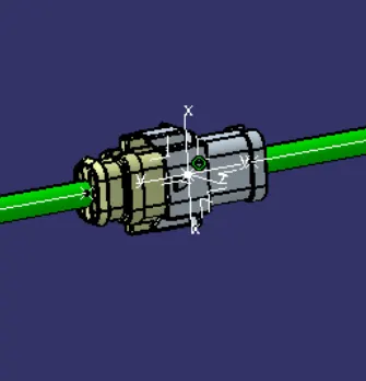
Harness are connected
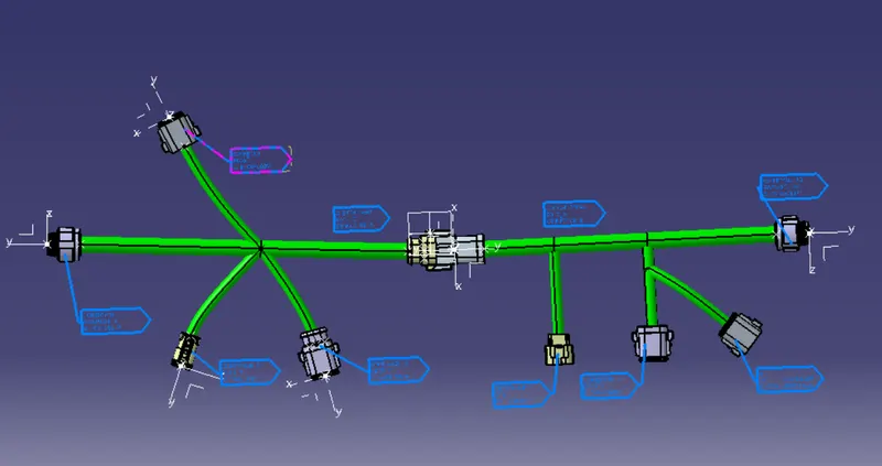
HARNESS ASSEMBLY
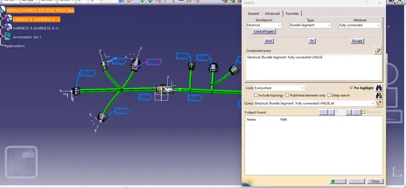
CHECK FOR BUNDLE CONNECTIVITY
HARNESS A
Edit---> Search--->Advance
Workbench---->Electrical
Type------>Bundle Segment
Attribute----> Fully connected
Attribute Criterion-----> TRUE
so it will select automatical and shows the connected Bundles
IF we select Pre Highlite
Annotation Creation
for creating Annotation we need to jump to Mechanical Assembly Workbench
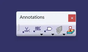
Select the annotation type and select the Plane on which we need to create the annotation
Annotation are created
Harness B side Annotation
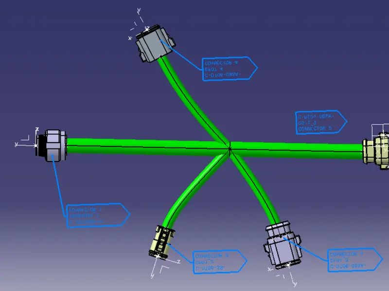
Harnes A Side Annotation
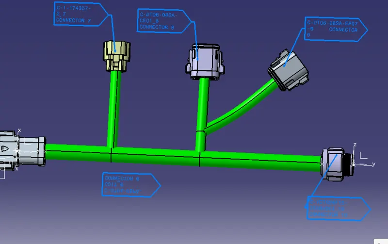
Harness Annotation

BUNDLE WARNING
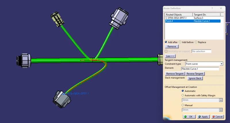
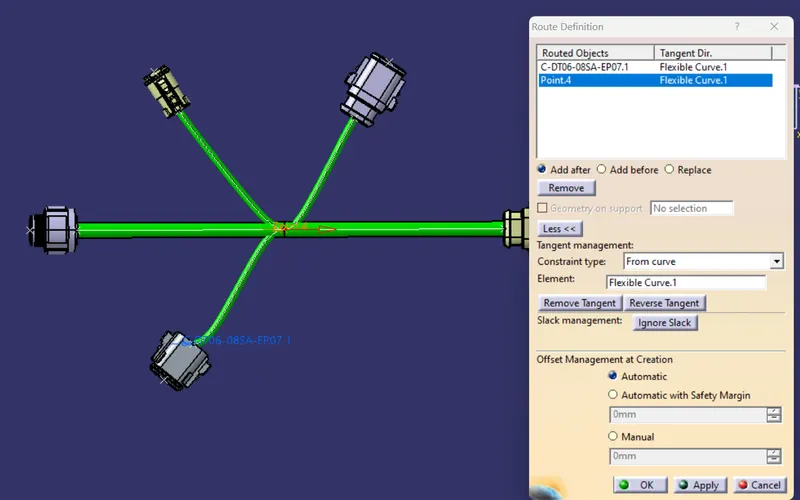
Due to Reverse in Tangent Direction it is showing warning we can sove by reversing the tangent Direction
Problem solved
Converting Product File to Part File
To convert go to mechanical Assembly Work Bench
Tools---->Generate CATPart from Product...
click on the product icon and OK
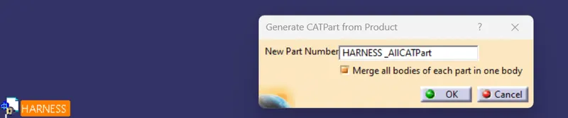
so Product is Converted To CATPart
Now covert them into STP and IGS file Using Save AS Option
Conclusion
Harness Assembly is created By using Connectors DATA and Harness Layout
Mechanical Parts are defined as Electrical Components
Anootations are Created
Bundle Conntunity is Checked
Product is Converted as PARt file , STP and IGS format.
Catalouge is ceated for Connctors and imported in assembly