Wiring harness design in CATIA V5 - 3D modeling Week 5 & 6 Challenge
Objectives :
Route the following harness layout in Electrical workbench. Make assumption for harness bundle diameters. Use the connectors provided. After completion of routing
- Check the bundle Continuity.
- Add annotation to all connectors.
- Check for the bundle warning.
- Generate CAT.part of harness assembly and convert it in. igs format.
Procedure :
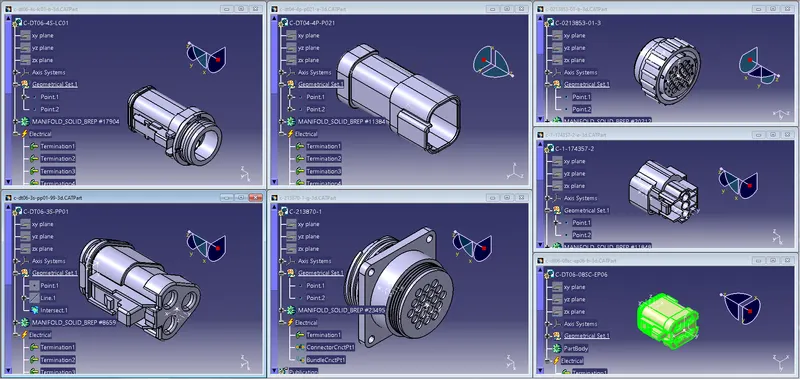
1. Defining Connectors :
Define all the electrical connectors geometrically and electrically so that they can be used in the wiring harness. Giving them connector connection and bundle connection defination.
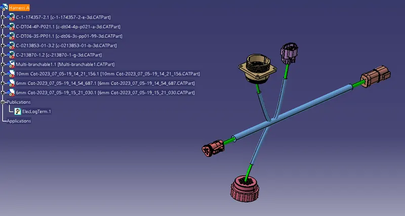
2. Ceating HARNESS A
After all the connectors are defined, the workbench was switched to Electrical Harness Assembly where Geometrical Bundle was activated. All the connectors were routed using the Multi-Branchable Document command.
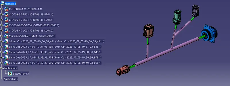
3. Creating HARNESS B
After all the connectors are defined, the workbench was switched to Electrical Harness Assembly where Geometrical Bundle was activated. All the connectors were routed using the Multi-Branchable Document command.
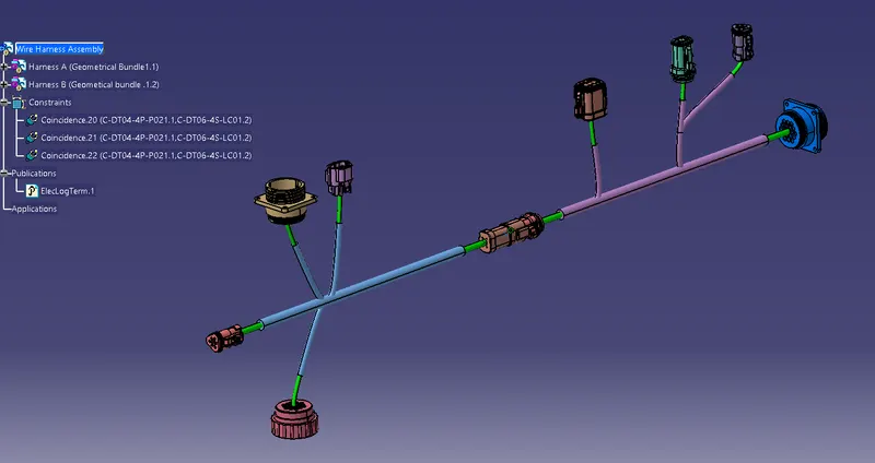
4. Creating HARNESS ASSEMBLY
Connect the Harness A and Harness B. With the help of connect electrical devices.
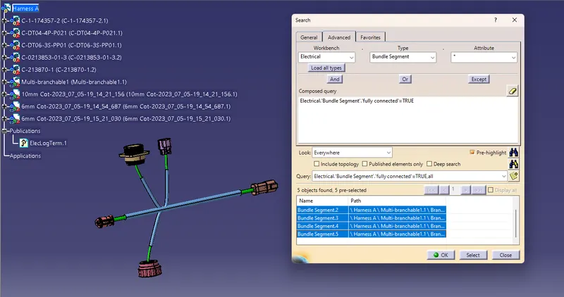
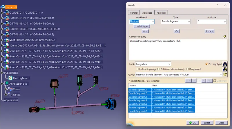
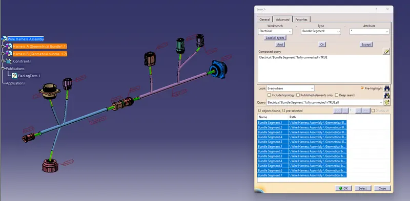
5. Checking Connectivity :
Go to Edit, Select the Search, in search go to Advance. In Advance, in workbench select the Electrical, in Type select the Bundle Segment, in Attribute select the Fully Connected option.
Harness A
Harrness B
Assembly
6. Geometrical bundle Warnings
It is possible to get warnings when routing your wire harness. These warnings are usually displayed in the tree structure of the wire harness geometrical bundle.
These warnings are usually related to the bend radius, bundle diameter or the vector position of your bundle segments. If there are any issues with the above then a yellow flash warning symbol will appear in the tree structure of the geometrical bundle.
Note: To solve the warnings given by the bundle segments, the clips and connectors positions can be changed. In case if it is not possible to change the positions, then by using Tangent management of external points with the external lines form curve, the error can be resolved.
7. 3D Annotations
The 3D annotation is used on the wiring harness to show connector functions and additional notes.
Connector function annotation: This annotation is to be added to the connectors to show the function of the connector unit it is connecting to. This is useful for other design departments who requires the 3D harness models but aren’t familiar with the harness connector functions.
Wiring harness drawing notes: This annotation is to be added to the harness data to show specific information relating to the harness (wire type, wire specifications, or any additional information/comments that need to be specified).
Creating the annotation:
- Switch to Assembly Design Workbench.
- Make sure the Geometrical Bundle is Active.
- Select the front view/ annotation plane icon.
- Select the plane for the annotation.
- Select the flag note with ladder icon.
- select a reference point to add the annotation.
- Input the connector function name.
- Select ok.
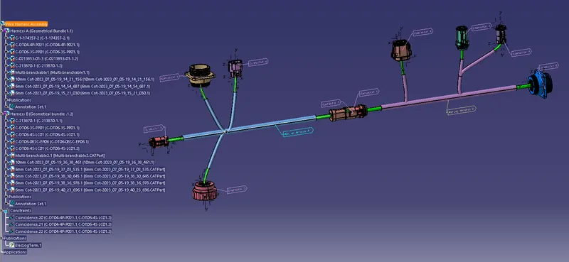
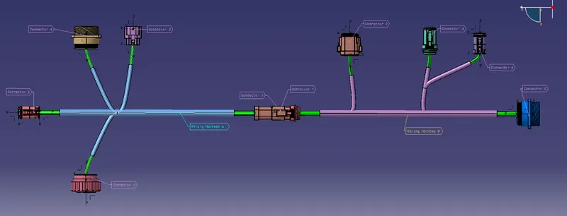
8. Converting as a part body and save as IGS Forma
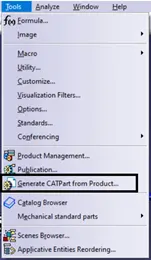
To create a CAT part of the 3D wire harness for Review or releasing purposes. This CAT part can be converted as IGES or STEP.
Go to Mechanical Assembly Workbench, Tools, Generate CATpart from Product.
Conclusion :
- Routed the harness layout in Electrical workbench.
- Checked the bundle Continuity.
- Added annotation to all connectors.
- Checked for the bundle warning.
- Generated CAT.part of harness assembly and convert it in .igs format.