Wiring harness design in CATIA V5 - 3D modeling Week 5 & 6 Challenge
Aim:
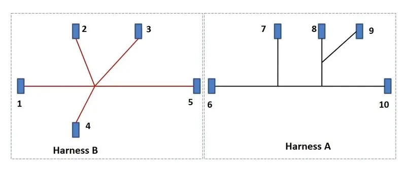
To design the given harness layout in electrical workbench.
Objective:
- First route the two harness A & harness B as per given harness layout.
- Check the bundle Continuity
- Add annotation to all connectors.
- Check for the bundle warning.
- Generate CAT. Part of harness assembly and convert is in. igs format.
Step 1
Define all the connectors geometrically and electrically.
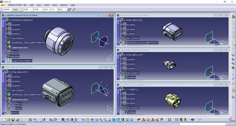
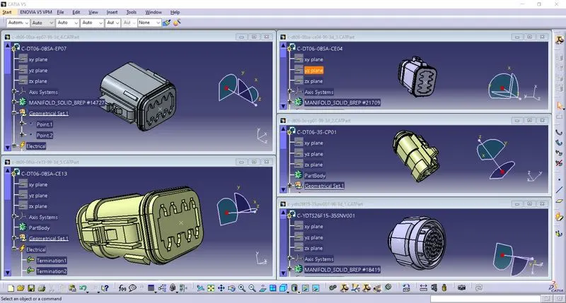
Step 2
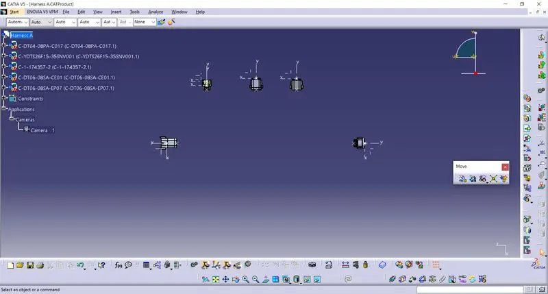
First all the connectors are placed in given layout diagram in assembly design.
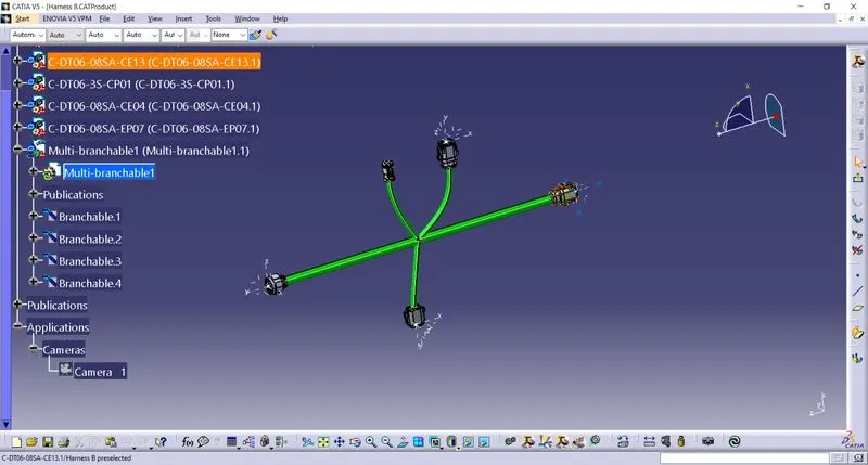
Layout of Harness B
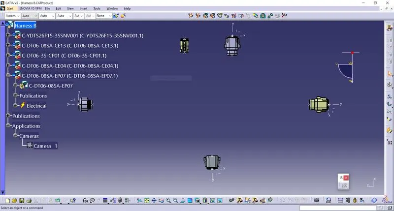
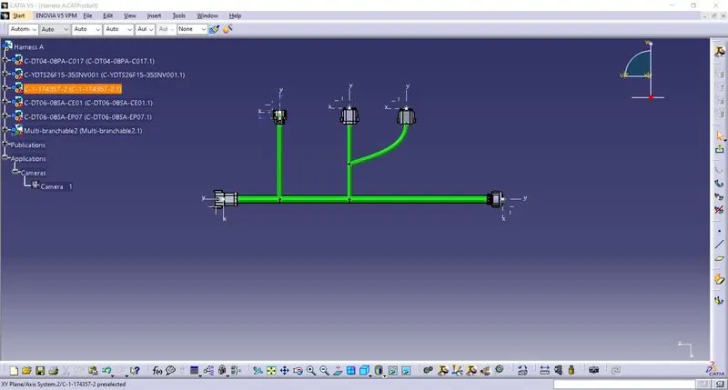
Layout of Harness A
After change the workbench in electrical harness assembly. Assumed the bundle diameters is 10mm and 15mm of the bundle segments.
Step 3
After Harness A & Harness B are checked in the bundle continuity.cted and then we have to go in
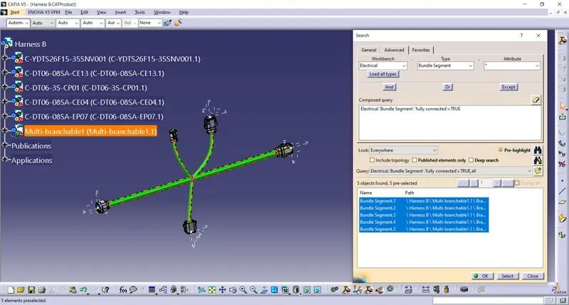
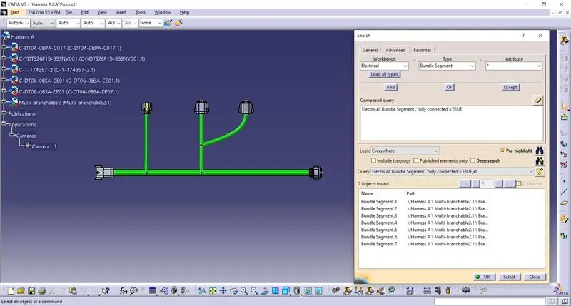
Edit > Search > Advanced > Electrical workbench >Type-Bundle segment > Attribute – Fully Connected.
Selecting the “TRUE” option will show all the connected bundle segments while selecting “FALSE” option will show all the non connected bundle segments.
We will select the “TRUE” option and search for the results. Harness A & Harness B bundle segment continuity shown in display.
Step 4
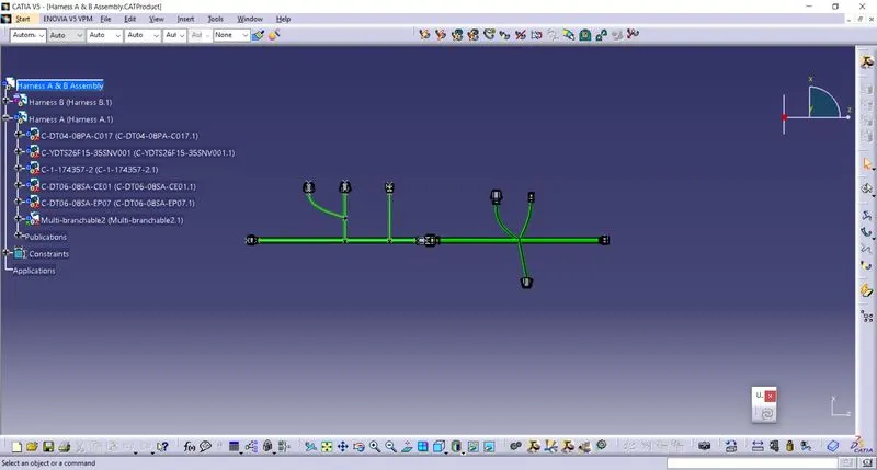
We have to interconnect the wiring Harness A & Harness B electrically.
First make the new product and rename it. After insert the electrical assembly of Harness A & Harness B cad files. We are inside the electrical assembly design workbench we should electrical connect the male and female connectors as shown in bleow.
Step 5
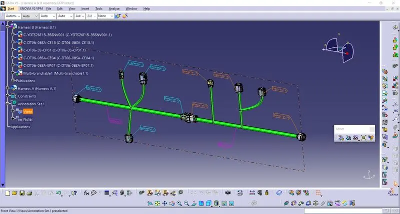
We will be adding annotations for the all electrical connectors. First, we have to choose the plane on which the annotation will be placed. Select the flag note with ladder function and then click on connectors individually. After annotation are added to all the connectors of Harness A & Harness B assembly.
Step 6
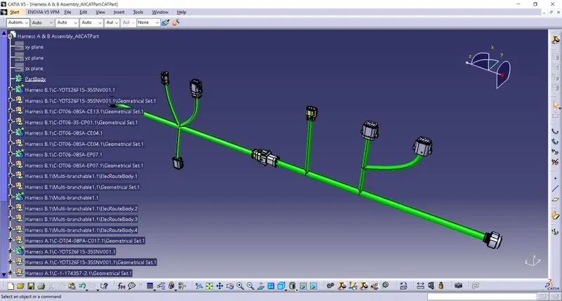
We have to convert out final harness assembly file into igs format. Once the CAT part is created the whole product file is converted into a single part. At in the stage it can be noticed that all the bundle segments are grey color after change the bundle segments color. After save as the CAD Part in IGS format.
Conclusion
Routing of the two electrical harness as per given layout was achived and interconnecion between the as a single harness assembly is finshed. Both the harness were checked and correct the bunndle segments. Annotation is added the all connectors and convert the IGS format.