Wiring harness design in CATIA V5 - 3D modeling Week 5 & 6 Challenge
Aim :
Route the Given harness layout in Electrical workbench & Apply the Conditions.
Ojectives :
- Check the bundle Continuity. Add snap of result in submission
- Add annotation to all connectors. Make an assumptions for annotations like connect 1 , 2 etc
- Check for the bundle warning. Add snap.
- Generate CAT.part of harness assembly and convert is in. igs format.
Procedure :
1st Connector of Harness B :
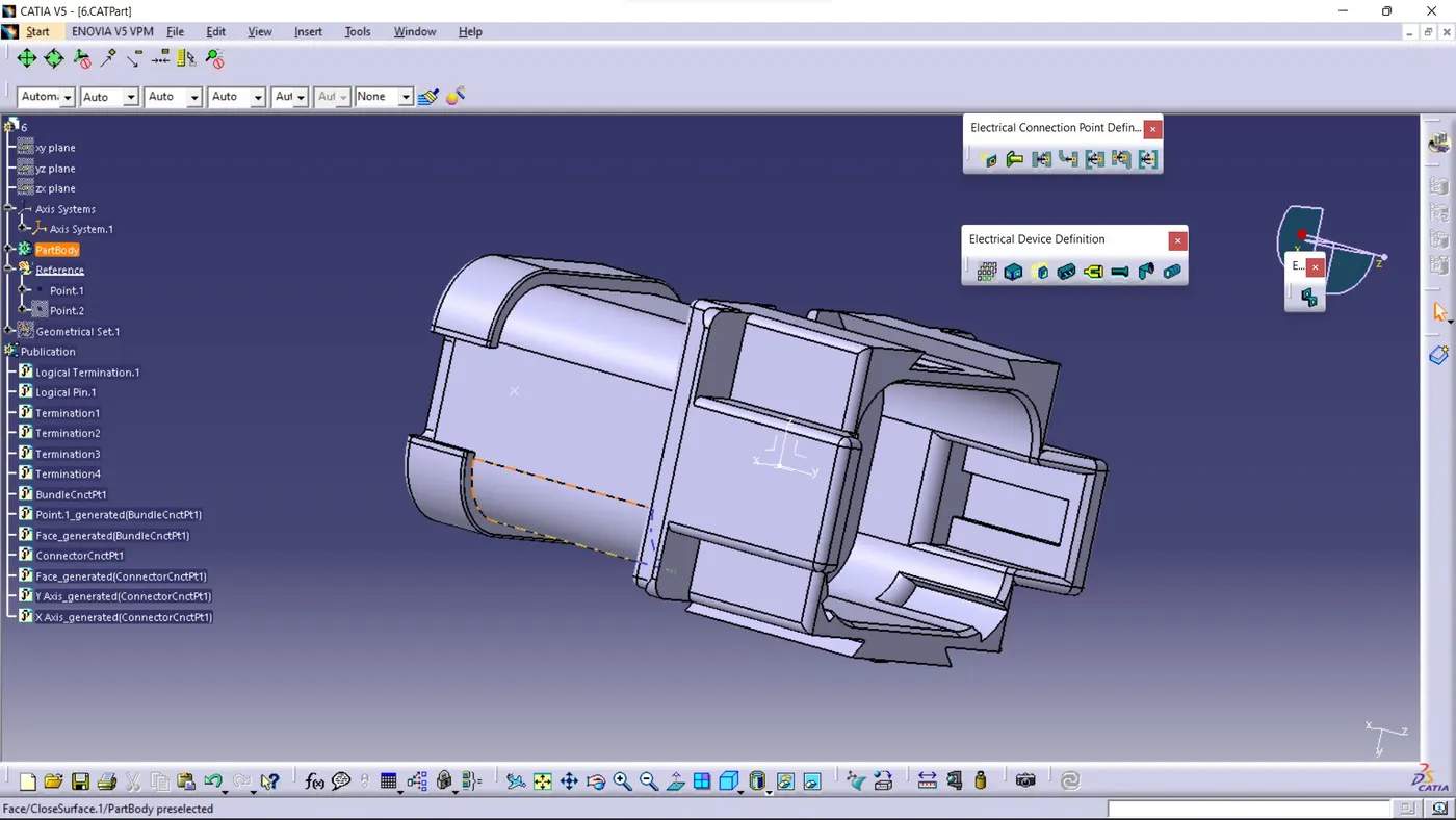
In the Above figure We Have Taken from given source & Merged into Catia V5.
1.Go To the Part design workbench & Taking A middle Point From The Connector Connecting Side As Well As Bundle Connecting Side.
2.Taking the axis Origin of Connector connecting Point.
3.Adusting the y-axis is normal to the face of connector connecting Point & X-axis would be locking side & Z-axis would be Up or down side.
4.Then go to the electrical part design workbench after that defined it as a connector & Add no of terminals it has & defining the connector connection point As well as bundle connection point with respect to their faces & Respresentations.
2nd Connector of Harness B :
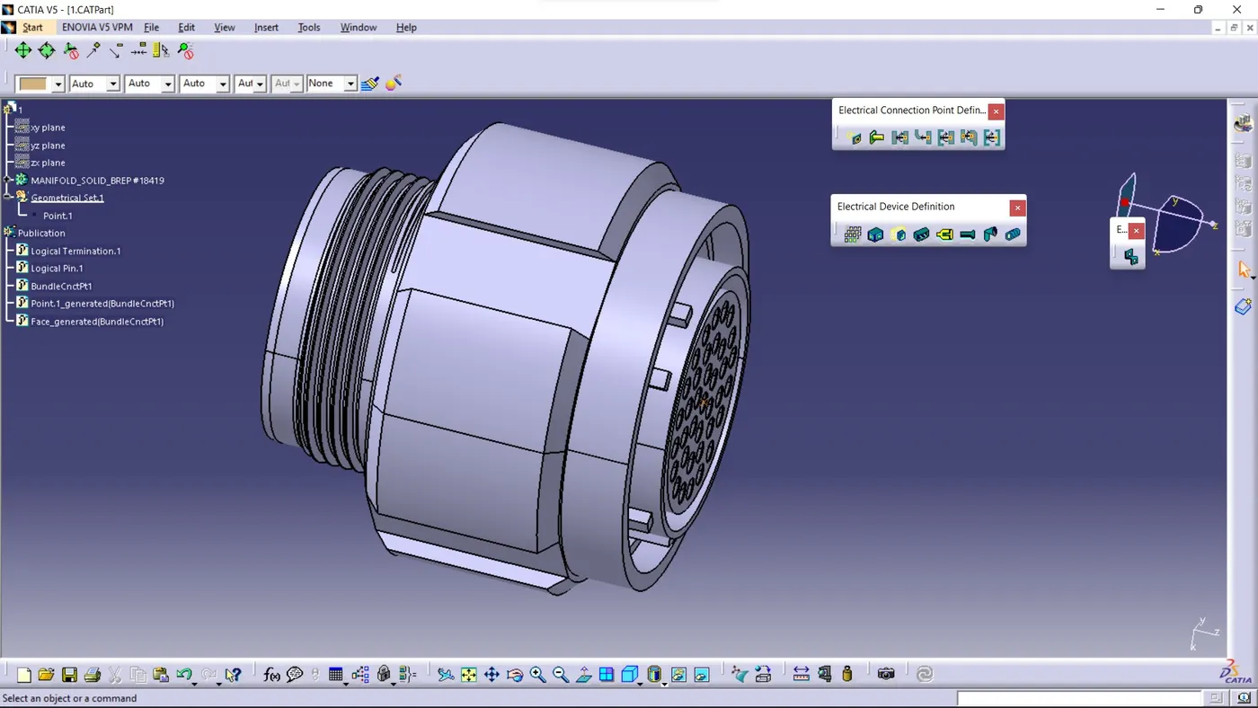
In the Above figure We Have Taken from given source & Merged into Catia V5.
1.Go To the Part design workbench & Taking A middle Point From The Connector Connecting Side As Well As Bundle Connecting Side.
2.Taking the axis Origin of Connector connecting Point.
3.Adusting the y-axis is normal to the face of connector connecting Point & X-axis would be locking side & Z-axis would be Up or down side.
4.Then go to the electrical part design workbench after that defined it as a connector & Add no of terminals it has & defining the connector connection point As well as bundle connection point with respect to their faces & Respresentations.
3rd Connector of Harness B :
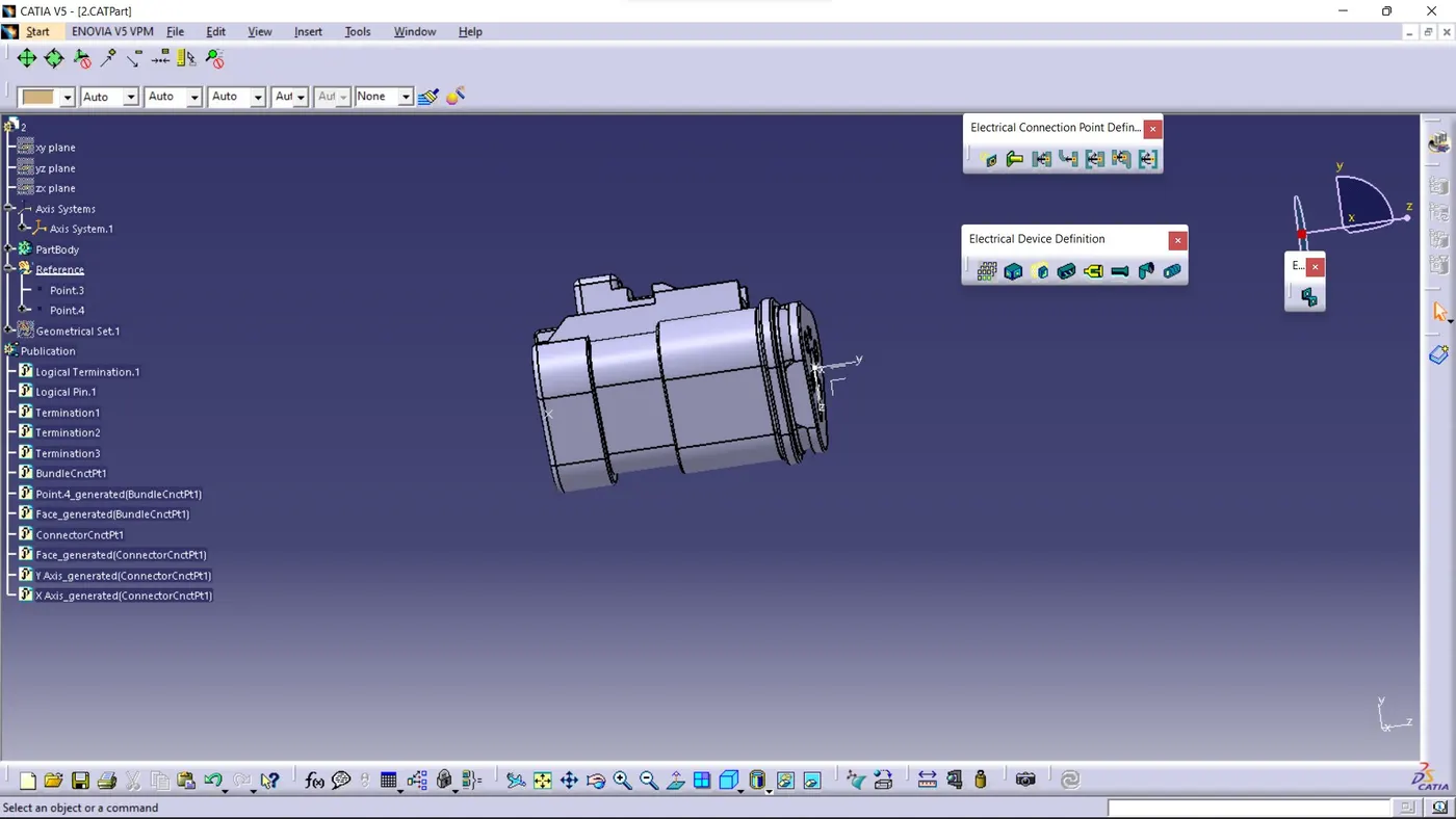
In the Above figure We Have Taken from given source & Merged into Catia V5.
1.Go To the Part design workbench & Taking A middle Point From The Connector Connecting Side As Well As Bundle Connecting Side.
2.Taking the axis Origin of Connector connecting Point.
3.Adusting the y-axis is normal to the face of connector connecting Point & X-axis would be locking side & Z-axis would be Up or down side.
4.Then go to the electrical part design workbench after that defined it as a connector & Add no of terminals it has & defining the connector connection point As well as bundle connection point with respect to their faces & Respresentations.
4th Connector of Harness B :
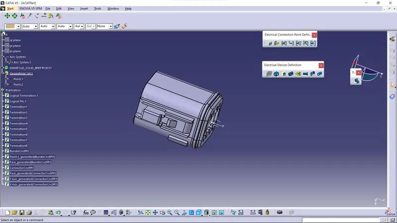
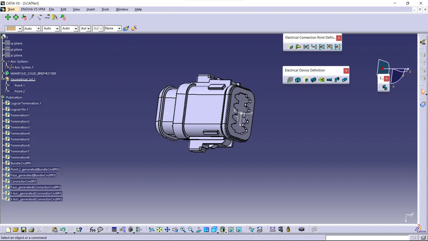
In the Above figure We Have Taken from given source & Merged into Catia V5.
1.Go To the Part design workbench & Taking A middle Point From The Connector Connecting Side As Well As Bundle Connecting Side.
2.Taking the axis Origin of Connector connecting Point.
3.Adusting the y-axis is normal to the face of connector connecting Point & X-axis would be locking side & Z-axis would be Up or down side.
4.Then go to the electrical part design workbench after that defined it as a connector & Add no of terminals it has & defining the connector connection point As well as bundle connection point with respect to their faces & Respresentations.
5th Connector of Harness B :
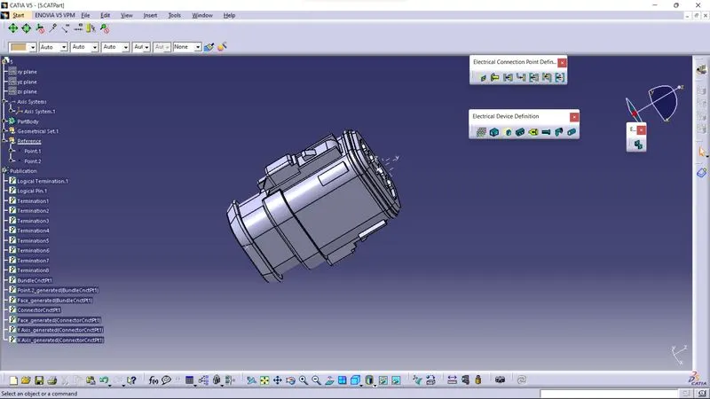
6th Connector of Harness A :