Wiring harness design in CATIA V5 - 3D modeling Week 5 & 6 Challenge
Ans 1
Objectives
- Downloading the following connectors cad data from the given link
- Defining the Electrical Connector using the Electrical Part Design Workbench.
- Use the following connectors as shown in the layout diagram.
- Route the following harness layout in the Electrical workbench
- Check the bundle Continuity. Add a snap of the result in the submission
- Add annotation to all connectors. Make assumptions for annotations like connect 1, 2, etc
- Check for the bundle warning. Add snap.
- Generate CAT.part of harness assembly and convert it in. igs format.
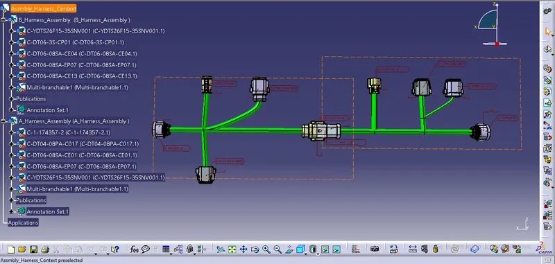
The layout to follow in this project.
Connector
It is an electro-mechanical device used to join electric terminations and creates electric circuits.
https://drive.google.com/drive/folders/1U7uyPj5zw9uQ3XJlIJTi9ti-MzvpDNqG?usp=sharing
By using the above link we download the required part for our work
The following types of connectors are used in this project are
- B Harness Assembly
- c-ydts26f15-35snv001-99-3d
- c-dt06-3s-cp01-99-3d
- c-dt06-08sa-ce04-99-3d
- c-dt06-08sa-ep07-99-3d
- c-dt06-08sa-ce13-99-3d
- A Harness Assembly
- c-dt04-08pa-c017-99-3d
- c-1-174357-2-e-3d
- c-dt06-08sa-ce01-99-3d
- c-dt06-08sa-ep07-99-3d
- c-ydts26f15-35snv001-99-3d
After downloading the required cad file we now move forward with the creation of the various parameters for our connector. For the creation of various parameters, we require the following point in the parts.
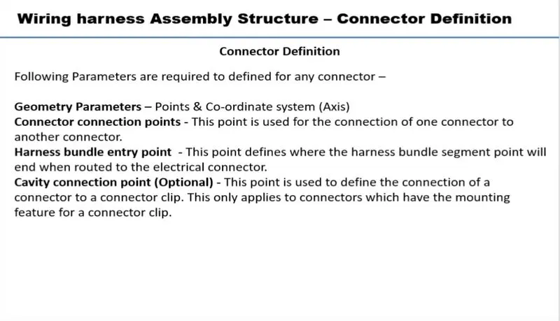
Bundle Connection Point
It is used to connect the wiring harness to the connector
for the creation of the bundle connection point, we create the point at the midpoint of the termination side of the connector.
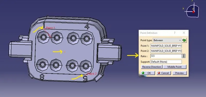
using the between type of point definition to create the point at the midpoint on the face select two points and give the ratio as 0.5 to create the required bundle connection point.
Connector Connection Point
It is used to connect the other device or connector to the main connector
using the same process to create the point at the midpoint at the other face of the connector which is directly opposite to the bundle face.
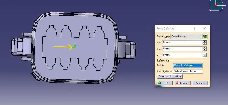
Axis
we must create the axis for the proper facilitation or for the proper seating of other parts with the connector.
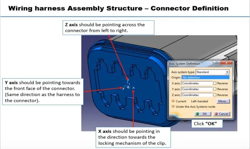
though these are not industry standards we need to be consistent with both mating parts in order to get proper assembly
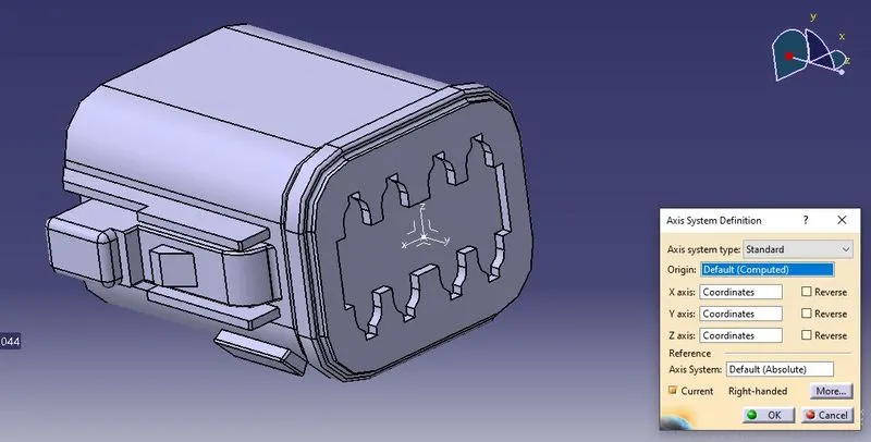
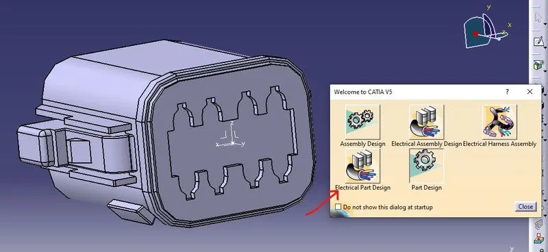
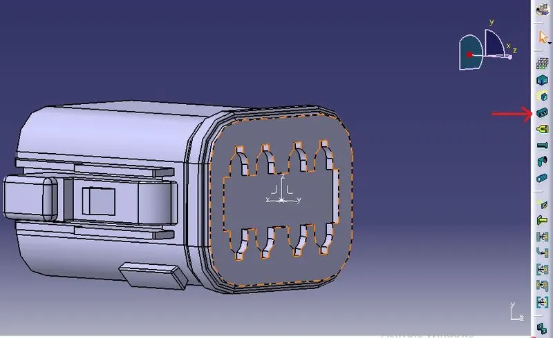
To convert the required part into the electrical component we use the define connector tool option
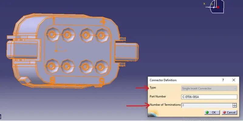
By simply choosing the connector type and the number of terminations we can easily define the part as an electrical connector.
We now need to define the various point we created in the part workbench in the electrical definitions for that we use the bundle connection point to define the Bundle connection
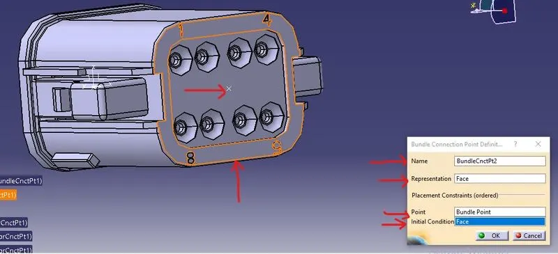
In the representation, we select the face which is normal to the bundle entry in the point we use the bundle point, and again in the initial connection we select the face which is normal to the bundle entry.
We now need to define the various point we created in the part workbench in the electrical definitions for that we use the connector connection point to define the connector connection
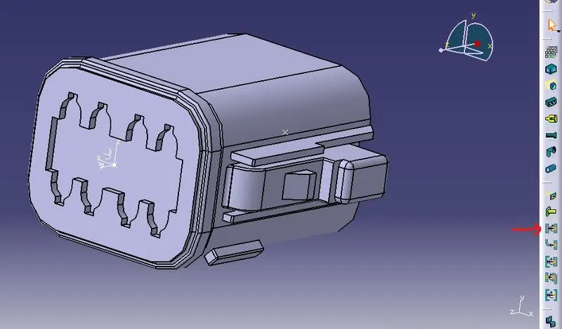
for that, we choose the representation as our already created connection point in the contact we choose which will go to be in contact with other mating parts we choose the coincidence axis as the Y axis where our parts move in and out for the assembly or in case of disjoining the parts and in the end we choose the orientation axis x-axis.
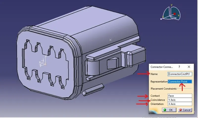
Similarly, we can use the same steps again for the other required parts.
After defining all the parts electrically we now move forward to save them in the catalog.
catalog
It is a document that keeps a list of references of other Catia parts and features which we can use these part whenever required.
Step 1
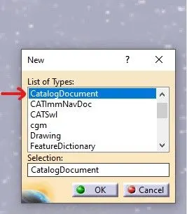
Clicking the New option present in the file tab and using the CatalogDocument in the new option to form the new catalog file for the same.
Step 2
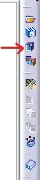
Using the add family option to open the new tab for the creation of a catalog
Step 3
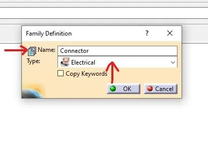
Giving the name of an electrical component for example connector and giving the type in the family definition as Electrical to save our electrical component in this catalog.
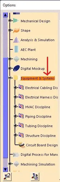
opening the options tool by drop downing the tool option and clicking on the equipment and system to further open the new options.
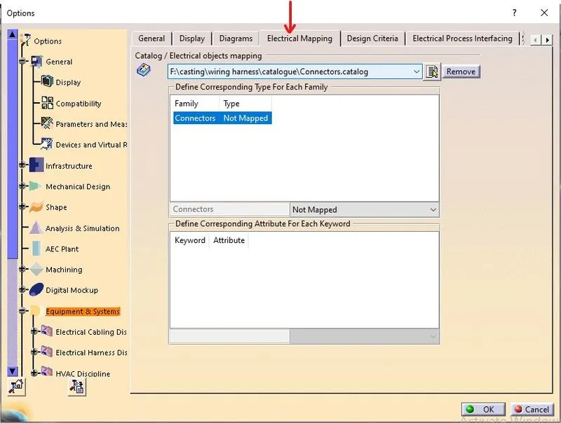
adding the Electrical mapping option to add the already created in the connector catalog.
for the storage of cad parts of electrical components
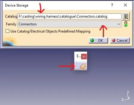
for storing the cad parts the storage option and giving the location of the catalog file in the catalog option and choose the required family in the family tab.
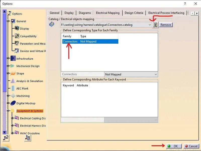
using the add file option in the mapping tab and selecting the required catalog file to add and then clicking ok to get the required catalog for further use in the future.
After saving connectors in the catalog, we move forward to assemble them.
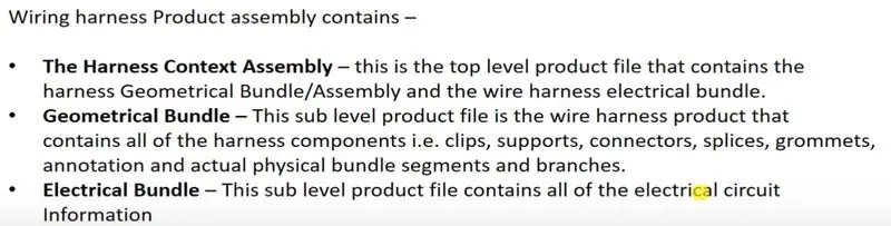
So for harness assembly, it contains many assembly files such as
Harness Context Assembly
As the name suggests, it is the assembly file that contains environmental data that provides information about the surrounding parts while assembling the wire harness, and before submitting the assembly file, we have to remove any kind of link between the surrounding electrical parts.
Geometric Bundle
It is the sub-level product file and contains all the harness products, i.e., clips, supports, connectors, grommets, and actual physical bundle segments and branches.
Inserting the components into the assembly
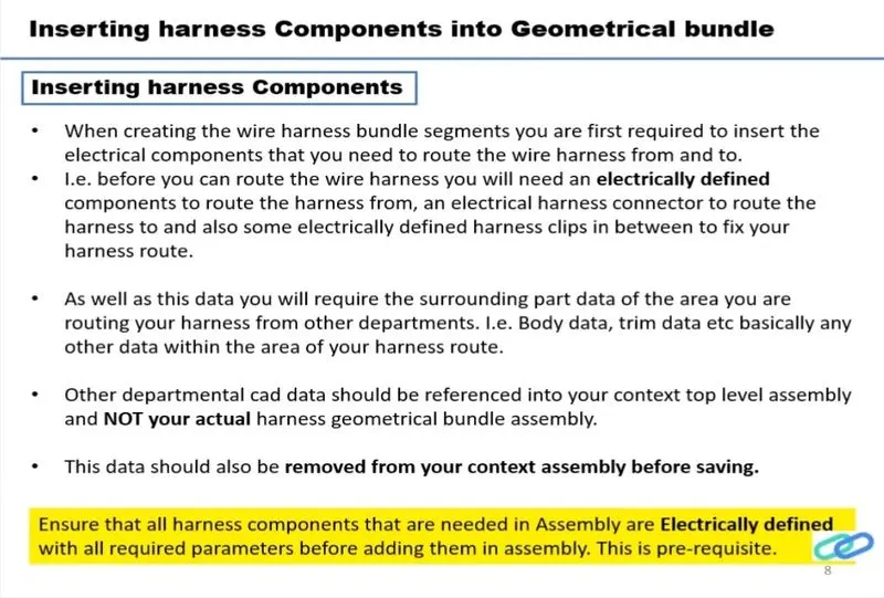
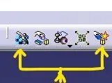
For inserting the components that are already electrically defined in the assembly, we use the browse catalog option from the browse catalog toolbar.
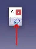
After opening the browse catalog toolbar, we can select the required connector from the list.
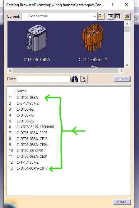
We can select the required number of connectors by double-clicking the required connector
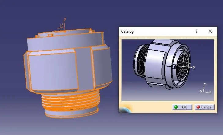
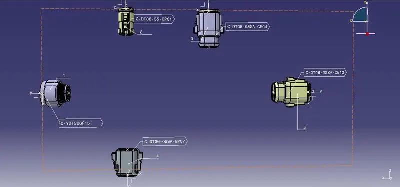
Hence, after selecting the required connectors for the required numbers, we now move on to the manipulating toolbar to properly place the required connectors for their respective distances and for the required orientation.
B Harness Assembly
A Harness Assembly
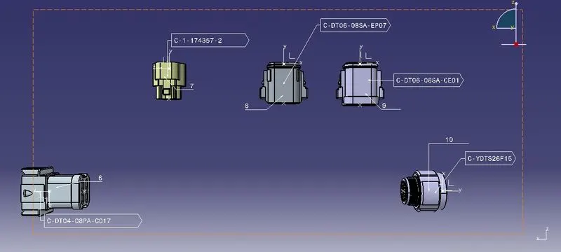
After placing the connectors in their required places, we now move on to convert the part assembly into the electrical harness assembly by using the electrical harness assembly workbench.
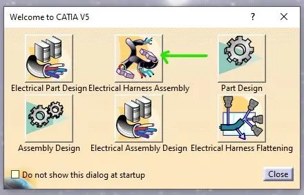
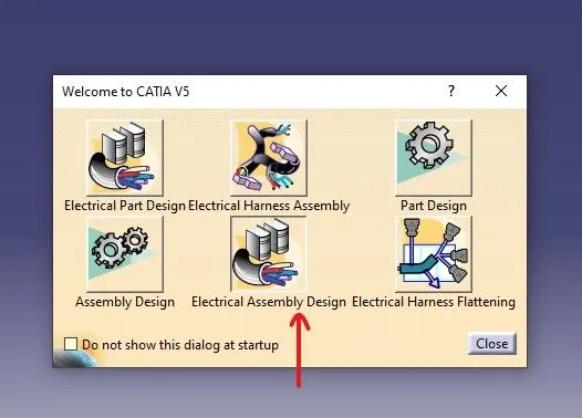
After going into the electrical assembly design, we now use the geometric bundle option to convert the normal assembly into the electrical assembly. We ensure the proper change of assembly into electrical by ensuring the change of the tool icon into an electrical tool icon.

 ------------->
For the making of the wire harness, we use the multi-branch document tool for the formation of the wire harness between the connectors.

A new window pops up named Branch Definition to give the diameter and bending ratio as the input for the new branch, where the bending ratio generally lies between 1.4 and 1.5 from the empirical relation.
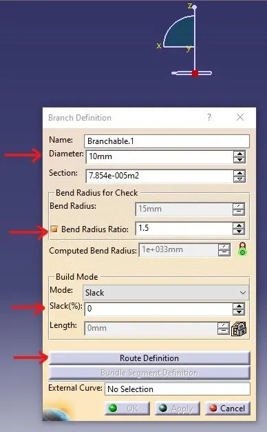
After giving the required parameter for the branch, we now move forward with the route definition to provide the proper route to the required bundle.
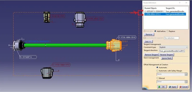
Here in the routed objects, we select the electrical components into which we require to make the bundles.
For splitting the bundle into two, we use the add branch point tool to divide the required bundle.

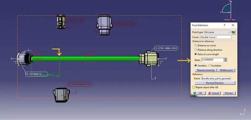
In the above image, we see the bundle, which is green in color, splintered into two parts at a distance that is required as per the question
Similarly, we are now able to create the bundle between the different connectors as per the diagram mentioned in the question.
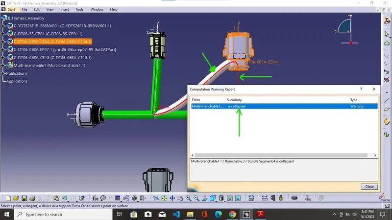
While moving forward with the completion of the wiring harness, we faced a warning. So in order to resolve the issue, we changed the direction of the bundle connection in the connector, and that's how we solved the warning.
Now we move forward with the final bundle connection.
B Harness Assembly
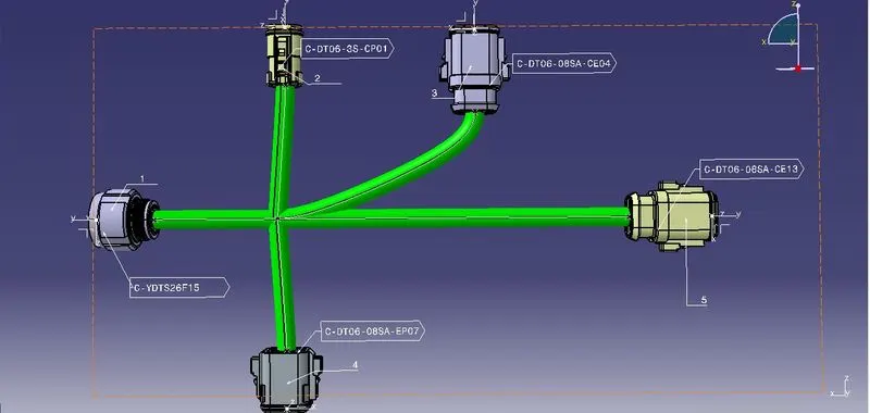
A Harness Assembly
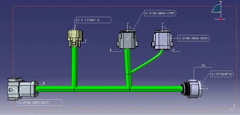
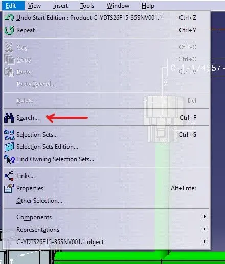
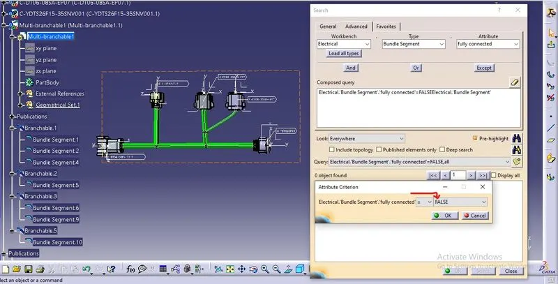
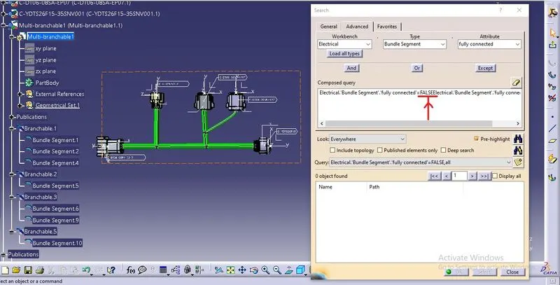
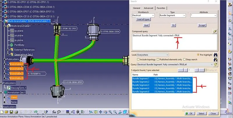
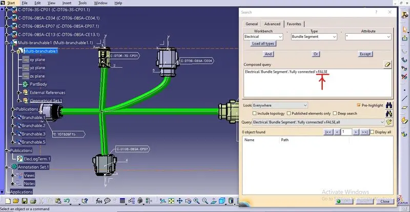
After the bundle harnessing, we now move forward to check whether the bundle connection is continuous or not. For that, we use the search tool present in the edit tab.
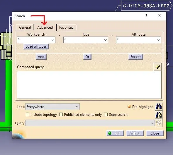
After that, we use the advance option in the newly opened window.
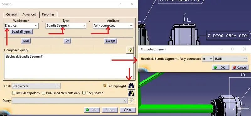
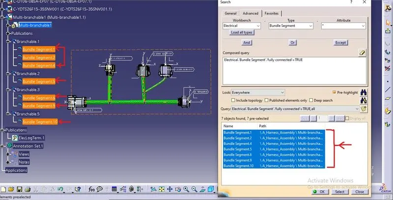
In the workbench definition, we give electrical in the dialogue box, and after that, in the type option, we provide bundle segment as a type, and to check the connection, we provide fully connected in the attribution definition. Now to see whether the bundle segment is fully connected, we use the true option. Then it shows the bundles that are connected to the main bundle segmented; if the bundles are not connected, then they will not be included in the list.
Now, instead of the true option, if we use the false option, it will show the segment that is not connected with the main bundle segment.
A Harness Assembly
B Harness Assembly
After checking the bundle segment continuity, if the whole bundle is continuous, we now move forward with the annotation of the connectors so that we can easily identify the parts when we work in a real environment or easily modify the cat part whenever required.
Annotation
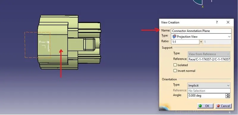
We employ the annotation toolbar to annotate the electrical components. which allows us to choose the reference plane, the platform upon which we annotate our parts, by choosing the view from the reference option.
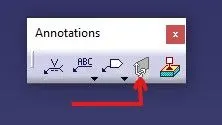
This plane serves as the reference plane for all the elements existing in the file and can be selected in the direction we want and given a new name.
Now for the annotation, we use the flag with annotation option in the annotation toolbar to annotate the desired property, name, and configuration to the desired component.
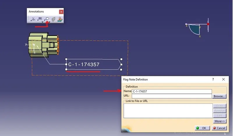
We follow the same step until every part gets the detailed annotation required in the file.
we now move forward with the interconnection between the different bundle segments of the wire harness
The following the method for the interconnection are:
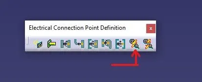
- using the connect electrical devices tool in the electrical assembly workbench to interconnect the two bundle segment.
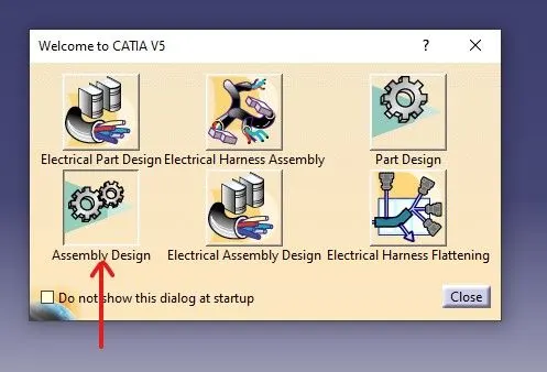
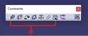
- By using a constraint toolbar available in the mechanical workbench assembly to interconnect the bundle segments
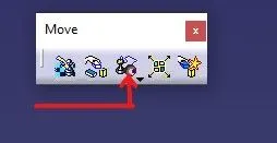
- by using the move toolbar available in the mechanical assembly workbench to simply manipulate the bundle segments to interconnect them with each other
By using the connected electrical device toolbar available in the electrical assembly workbench and then it will create the external reference point in the context assembly workbench which is not required so here we use the move toolbar to interconnect the two bundle segments. we use the snap tool to quickly join or interconnect that required bundling segments to connect them with each other
Through Connect electrical device
Through constraint toolbar
Through Move toolbar
final result after interconnection
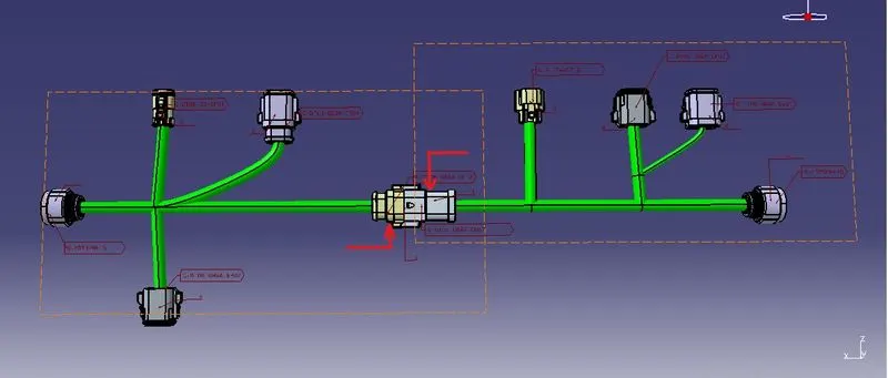
assembly file contains a large amount of data this data miss placed or a broken link occurs when we transfer the file from one software to another or there is a problem while converting the Assembly file from one software to another so we use the IGS file of the STEP file in order to reduce or to minimize the loss of the data while transferring the assembly file
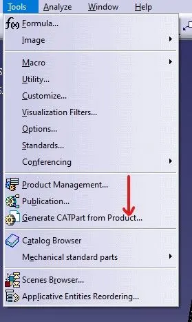
To convert the Assembly file into the catpart we use the tool generate catpart from the product present in the tools tab for the conversion process.
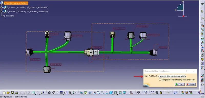
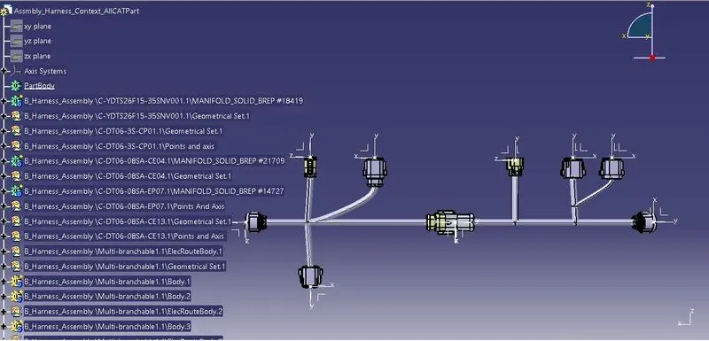
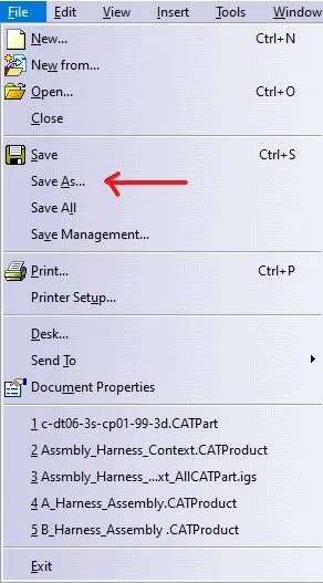
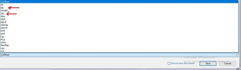
After the conversion of the assembly file into the catpart file we are now required to save it in the IGS or the STEP format in order to do that we use the save option for the final conversion into the required format.