Wiring harness design in CATIA V5 - 3D modeling Week 5 & 6 Challenge
Wiring harness design in CATIA V5 - 3D modeling Week 5 & 6 Challenge
Route the following harness layout in the Electrical workbench. Make assumptions for harness bundle diameters. Use the connectors provided. After completion of routing,
Convecting the Mechanical part into the Electrical part for that I have followed the steps.
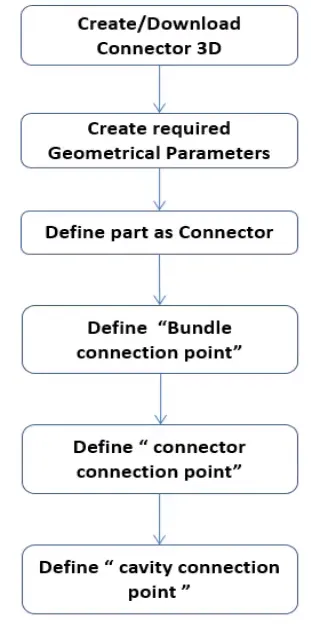
WIRING HARNESS_B
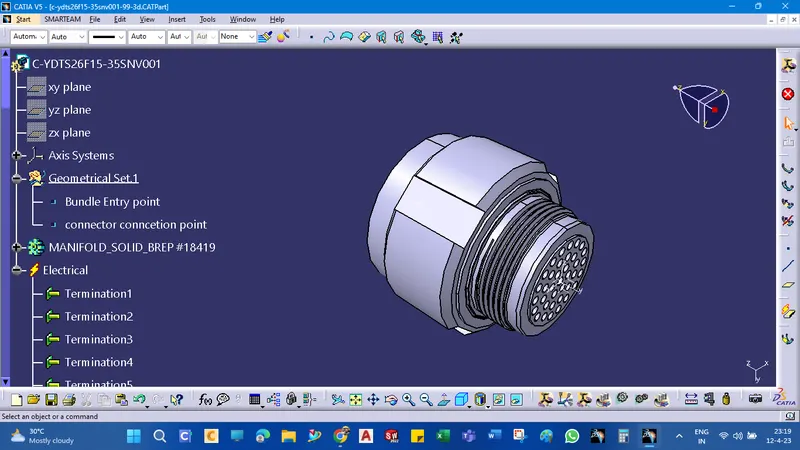
CREATIONS OF(C-YDTS26F15-35SNV001)
defined the connector as a 35-pin single-insert connector.
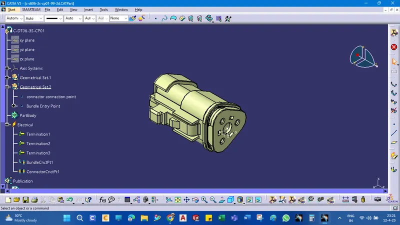
CREATIONS OF(C-DT06-3S-CP01)
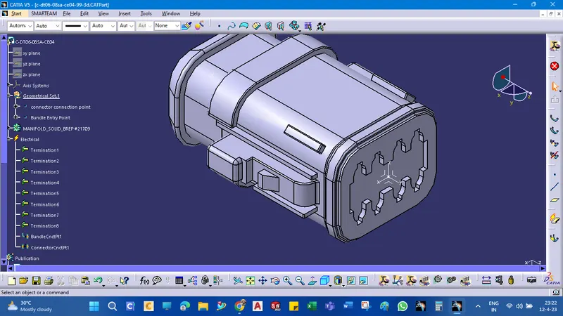
CREATIONS OF(C-DT06-08SA-CE04)
CREATIONS OF(C-DT06-08SA-EP07.1)
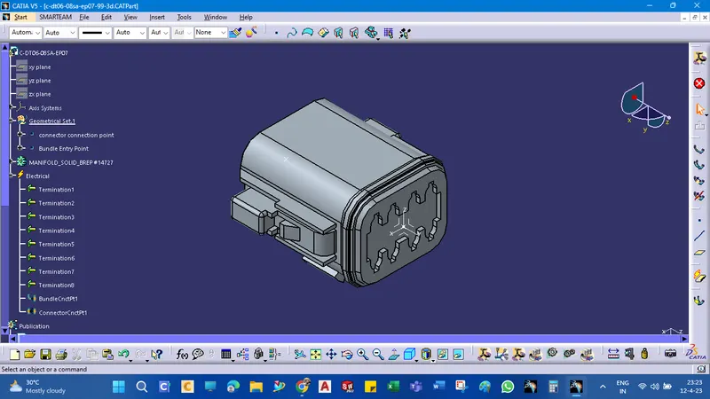
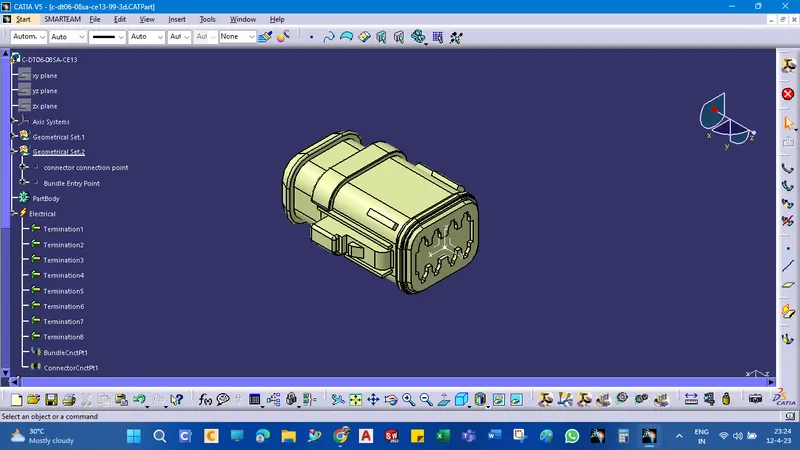
CREATIONS OF(C-DT06-08SA-CE13)
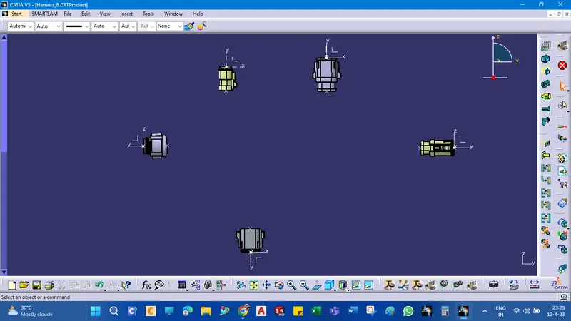
layout arrangements as given below
All the connectors are defined, and the workbench was switched to Electrical Harness Assembly where Geometrical Bundle was activated. All the connectors were routed using the Multi-Branchable Document command.
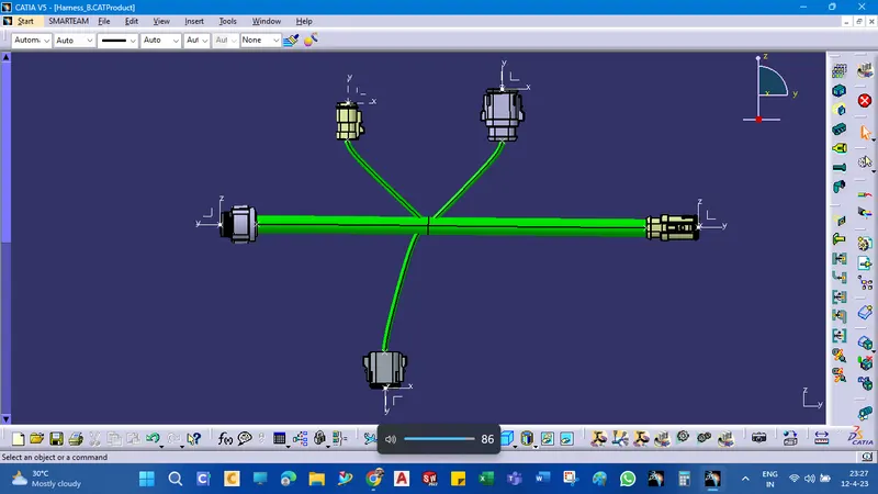
protective tubes creations
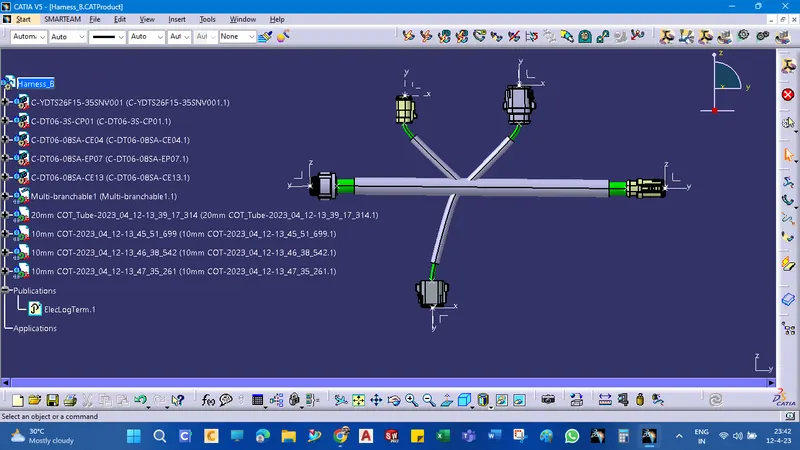
connectivity check
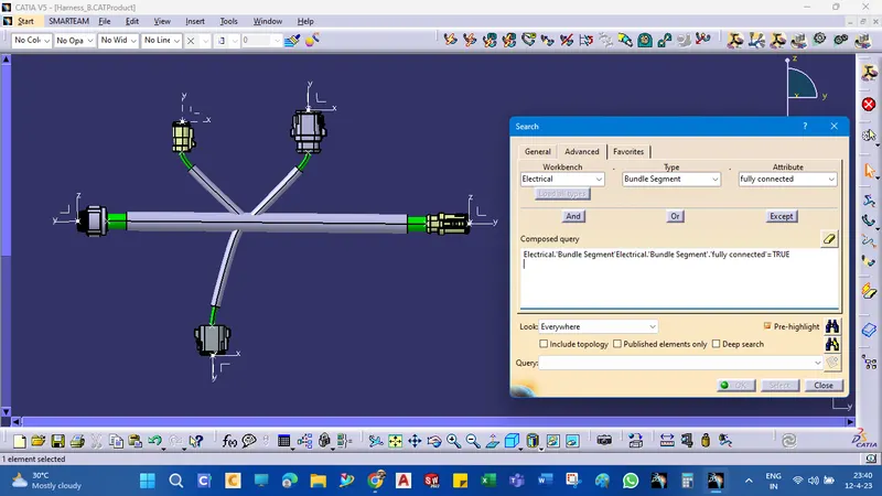
WIRING HARNESS_A
CREATIONS OF(C-DT04-08PA-C017)
The same is followed by the Harness_B creations method
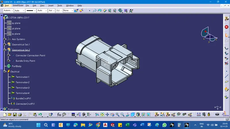
CREATIONS OF(C-1-174357-2)
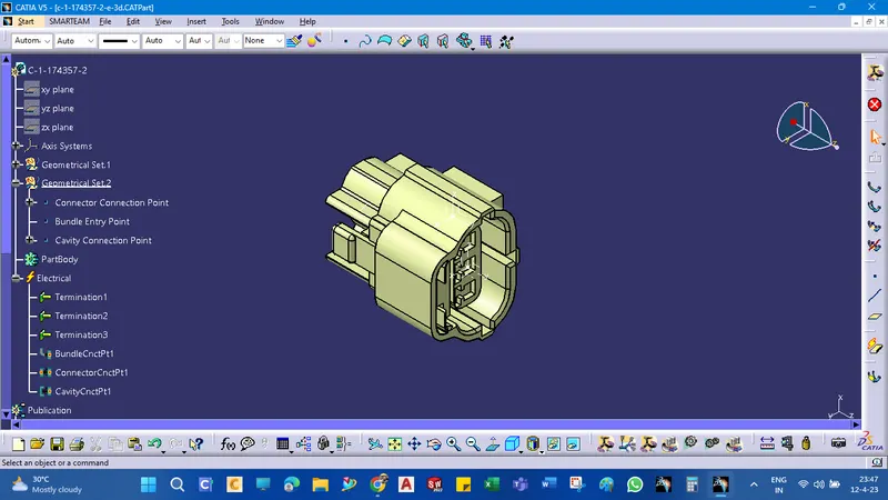
CREATIONS OF(C-DT06-08SA-CE01)
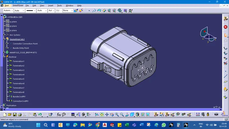
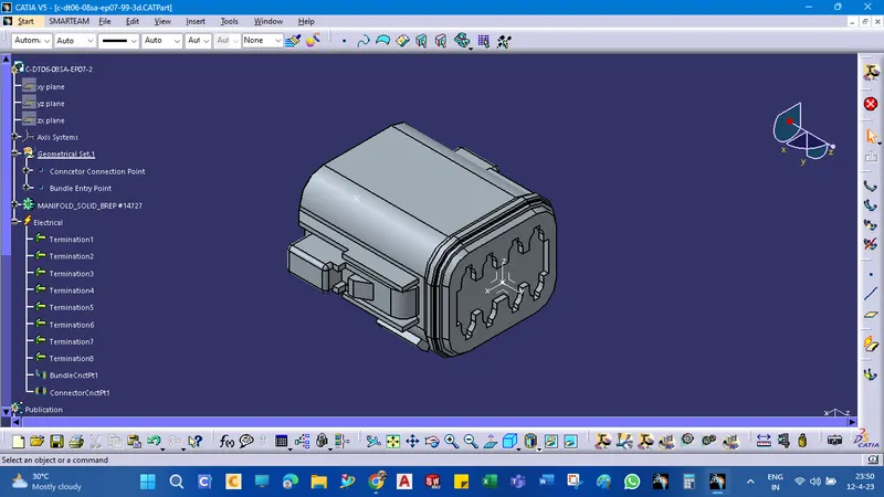
CREATIONS OF(C-DT06-08SA-EP07-2)
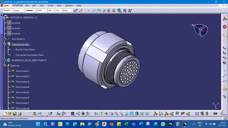
CREATIONS OF(C-YDTS26F15-35SNV001.1)
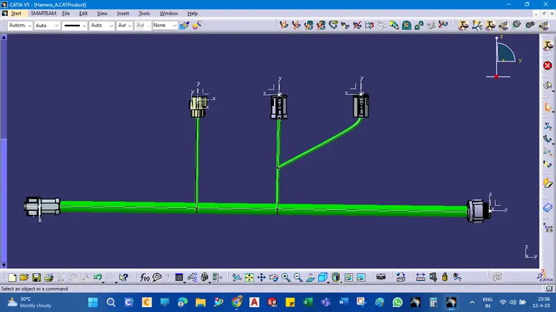
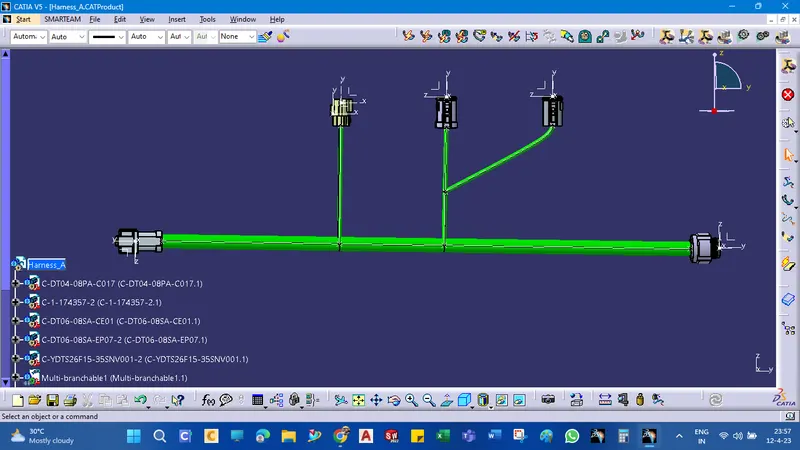
layout arrangements as given below
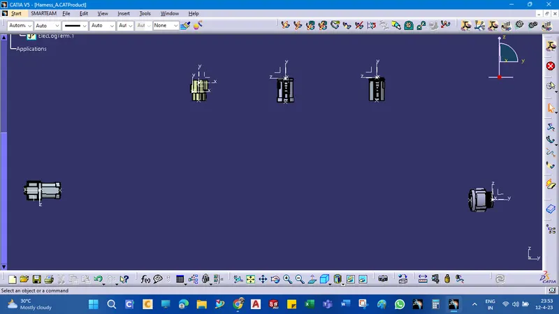
All the connectors are defined, and the workbench was switched to Electrical Harness Assembly where Geometrical Bundle was activated. All the connectors were routed using the Multi-Branchable Document command.
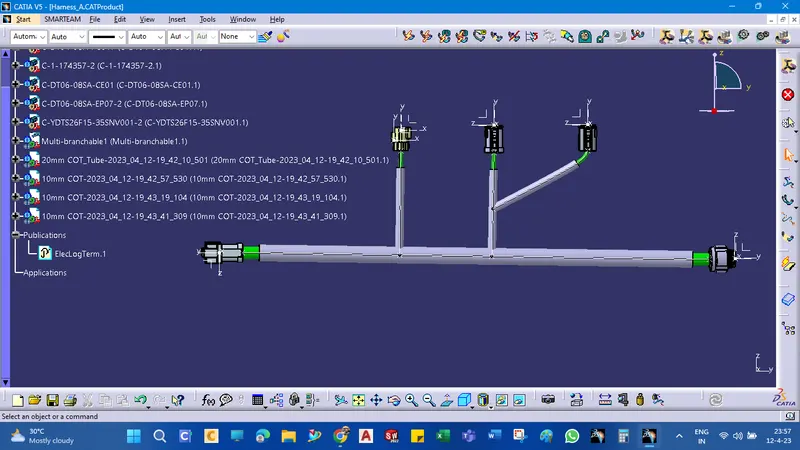
protective tubes creations
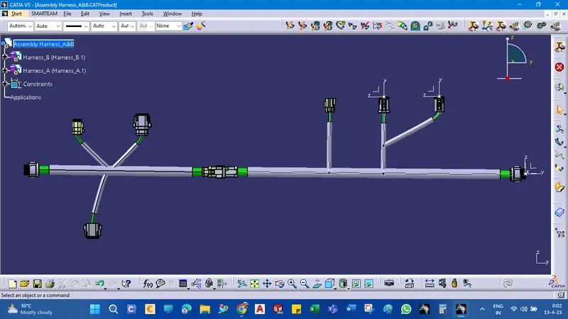
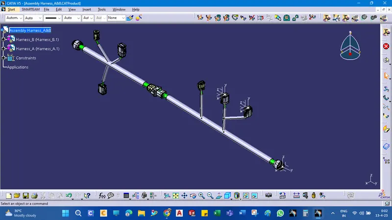
Final Assembly with Harness_B and Harness_A
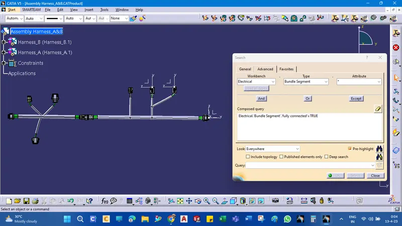
connectivity check
please refer to the attached zip file for more details