Hood design-Week 2
HOOD DESIGN USING NX CAD
WHAT IS HOOD?
The hinged cover of protection for the engine compartment.is called "HOOD". the car hood is a hinged cover that rests over the engine top of a vehicle. It provides access to the engine for repair and maintenance. A latch is typically used to hold down the hood. In some vehicles, hood pins may be used to hold down the car hood.
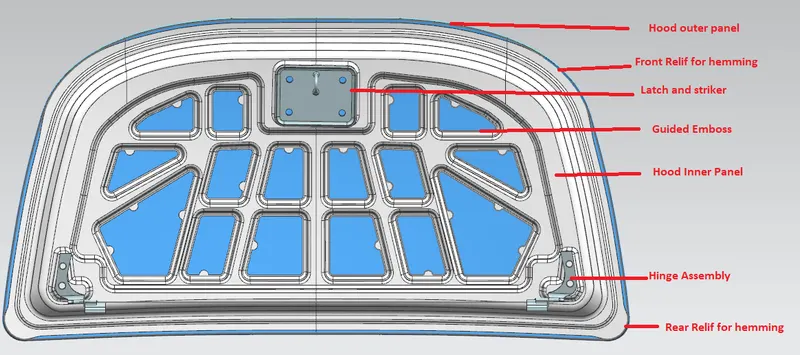
A hood assembly for a vehicle includes a hood having a top side and an underside. Also included is a hood latch-striker reinforcement plate operably coupled to the underside of the hood and having a retaining recess
OUTER PANEL
We can also call it a cover of the inner panel. It is the part, which gives luxurious look to the hood or bonnet. Outer & inner panel can not join by any welding process like spot welding or rivet, which spoil the outer look of a car. The outer panel has generally extracted the model from the prototype design
Hood inner panel and Latch Trajectory:
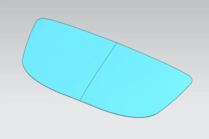
The inner panel is the part that gives strength and rigidity to the outer panel. The master section represents the initial emboss shape and size. Then we provide the emboss for the latch and hinge elements after fixing the location.
Latch Trajectory
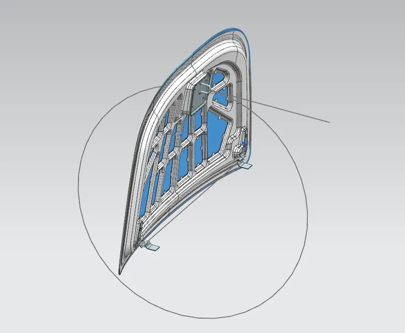
The latch trajectory is the path that the striker will follow when the hood is open/closed while pivoting on the hinge axis. The latch trajectory is taken as a circle with the hinge axis as the center of the circle. The striker is placed 90 degrees such that it is tangent to the circle.
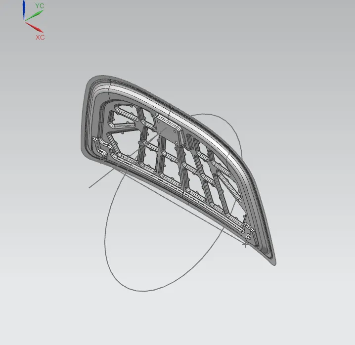
Latch Reinforcement :
Reinforcements are provided according to the design requirements. Mainly it is provided at the hinge and latch regions to improve the strength locally. Usually, the thickness of reinforcements will be higher than that of the inner panels and the value varies according to cost and requirement. According to the design requirement here, it is given 1.5mm thickness to both hinge and latch reinforcements.
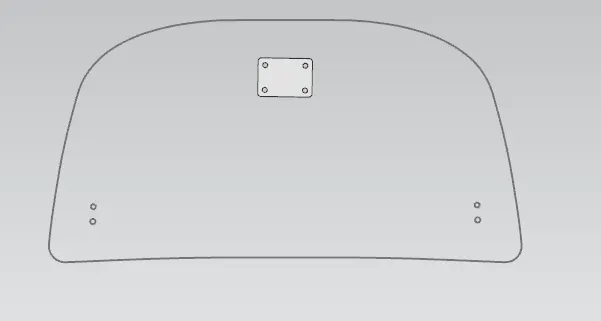
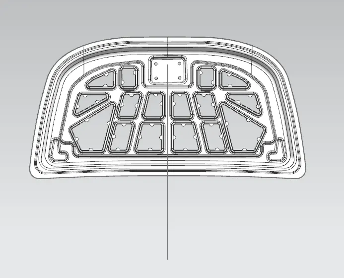
HOOD INNER PANEL :
A hood inner panel for a vehicle is provided to improve rigidity, durability, and pedestrian protecting performance by comprising a composite structure in which a multi-cone structure and a frame structure are individually arranged on the front and the rear.
MASTIC DATA :
WHAT IS MASTIC ?
Mastic is an adhesive that, along with thin-set mortar, is used to stick tile to wall or floor surfaces before grouting. While mastic does have strong points, such as great adhesive properties and adaptability to many substrata, high performance in wet areas is not one of its high points
Mastic in Details :
A Mastic is a rubberized, asphalt-based mastic. It has excellent adhesion to structural concrete, masonry, and
wood. The VOC (Volatile Organic Compound) content is 225 g/L. Architectural and industrial maintenance regulations
limit the VOC content in products classified as architectural coatings. Refer to Technical Letters for the most current
list of allowable limits. Mastic is available in tubes or pails.
Product Advantages :
Mastic is designed to seal terminations, edges of patches, and overlaps in detailed areas. On vertical
applications, the mastic must be applied to both the top and bottom terminations.
Limitation :
A Mastic is an integral part of the waterproofing system. This mastic should not be applied
where it will be covered with a waterproofing membrane, except as permitted as a temporary cutoff. It
should not be used as a primary waterproofing material.
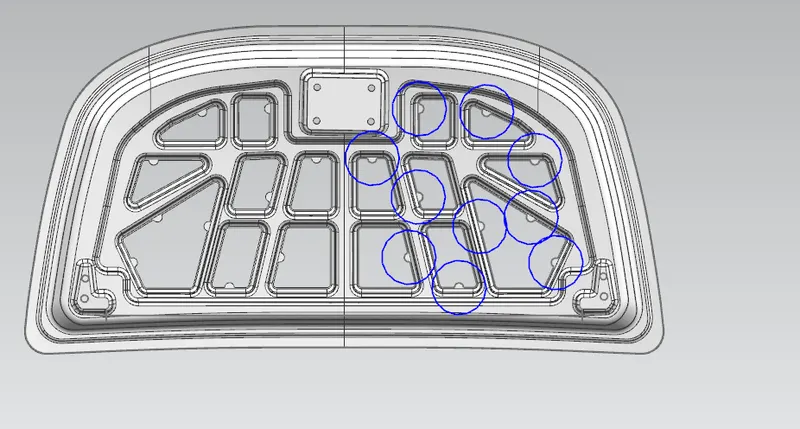
Fig: mastic Regions
Hinges :
A hood hinge mechanism has a pivot pin having a D-shaped cross-sectional shape positioned within a recess. The hood and pin are pivotal to a position whereat the D-shaped cross-section is oriented to pass through a slotted opening to the recess to thereby allow the hood to be removed or installed on the vehicle
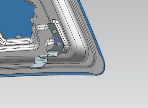
The process involved in designing a hood as a sheet metal operation,
Blanking,
Hemming,
Punch cutting, or piercing,
Deep drawing,
Embossing
Blanking :
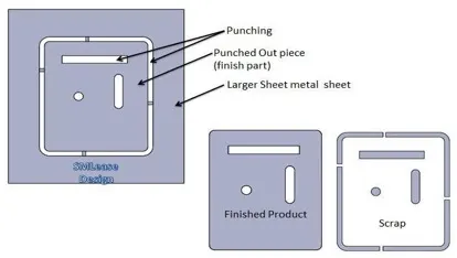
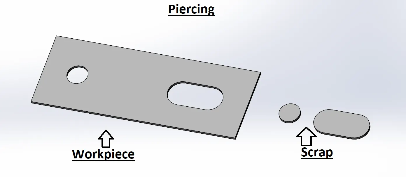
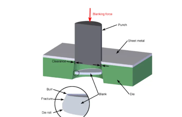
Blanking is a steel manufacturing process in which a flat, geometric shape (or “blank”) is created by feeding a coil of sheet metal into a press and die. In this process, the blank is punched out from a large metal sheet.
What is steel blanking?
Blanking is a steel manufacturing process in which a flat, geometric shape (or “blank”) is created by feeding a coil of sheet metal into a press and die. In this process, the blank is punched out from a large metal sheet. Here is a visual depiction of this process:

Press Blanking machinery can typically process material up to 72 inches (1828mm) wide and .250 inches (6.35mm) thick from coils up to 80,000 lbs. Typically multiple sheets are blanked in a single operation and the blanked parts will require secondary finishing to smooth out burrs along the bottom edge.
How does steel blanking differ from other processes?
Other, similarly natural processes include punching and piercing. Both remove material from a metal sheet but the end results differ from steel blanking.
Punching is also a material removal process but rather than the final product being the punched-out material, like in blanking, metal is removed so that the sheet metal itself is the final product. An easy way to differentiate is to think of a piece of paper that you punch a hole through. Blanking uses the circular piece as the final product while punching uses the piece of paper with the hole in it as the final product.
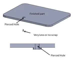
Another similar process is piercing, in which a punch operation cuts a hole by tearing an operation from a final piece of sheet metal. This is process is considered a blanking operation.
Hemming :
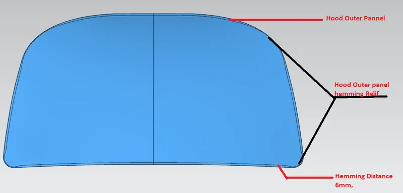
below is Given Hemming Data for this challenge to Follow the Hood Designing Process.
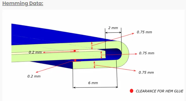
- Hemming is a sheet metal forming process in which sheets are joined by bending usually to 180 degrees. Automotive body panels & parts such as deck lids, trunk lids, doors, hoods & tailgates are formed by hemming processes.
- Roll hemming is carried out incrementally with a hemming roller. An industrial robot guides the hemming roller & forms the flange. Roll hemming operation can also be divided into several pre-hemming & final hemming process steps.
- Conventional die hemming is suitable for mass production. In die hemming, the flange is folded over the entire length with a hemming tool. Normally the actual hemming is a result of a forming operation in which the flange is formed with a hemming tool after the drawing & trimming operations have been completed.
Punch cutting, or piercing :
Punchcutting is a craft used in traditional typography to cut letter punches in steel as the first stage of making metal type. Steel punches in the shape of the letter would be used to stamp matrices into copper, which were locked into a mould shape to cast type
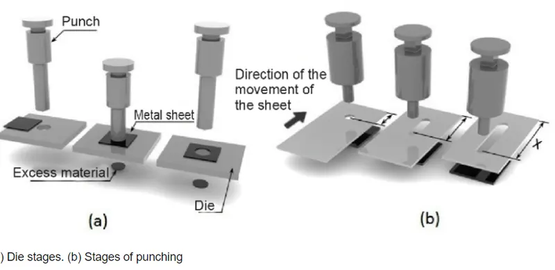
Punching (Piercing) It is the cutting operation with the help of which holes of various shapes are produced in the sheet metal. It is similar to blanking; only the main difference is that the hole is the required product and the material punched out to form a hole is considered a waste.
piercing :
Piercing is a shearing process in which raw metal is pierced with a machining tool, resulting in the creation of a circular or another shaped hole. As the raw metal is pierced, the metal from the newly created hole is considered scrap
Deep drawing :
Deep drawing is a sheet metal forming process in which a sheet metal blank is radially drawn into a forming die by the mechanical action of a punch. It is thus a shape transformation process with material retention. The process is considered "deep" drawing when the depth of the drawn part exceeds its diameter.
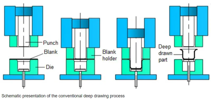
Deep drawing is a sheet metal forming process in which a sheet metal blank is radially drawn into a forming die by the mechanical action of a punch. It is thus a shape transformation process with material retention. The process is considered "deep" drawing when the depth of the drawn part exceeds its diameter. This is achieved by redrawing the part through a series of dies. The flange region (sheet metal in the die shoulder area) experiences radial drawing stress and tangential compressive stress due to the material retention property. These compressive stresses (hoop stresses) result in flange wrinkles (wrinkles of the first order). Wrinkles can be prevented by using a blank holder, the function of which is to facilitate controlled material flow into the die radius. Deep drawing presses, especially in the Aerospace and Medical industries, require unparalleled accuracy and precision. sheet hydroforming presses for complex draw work. Bed size, tonnage, stroke, speed, and more can be tailored to your specific draw forming application
Deep Drawings Process in Details :
The total drawing load consists of the ideal forming load and an additional component to compensate for friction in the contacting areas of the flange region and bending forces as well as unbending forces at the die radius. The forming load is transferred from the punch radius through the drawn part wall into the deformation region (sheet metal flange). In the drawn part wall, which is in contact with the punch, the hoop strain is zero whereby the plane strain condition is reached. In reality, mostly the strain condition is only approximately plane. Due to tensile forces acting in the part wall, wall thinning is prominent and results in an uneven part wall thickness, such that the part wall thickness is lowest at the point where the part wall loses contact with the punch, i.e., at the punch radius.
The thinnest part thickness determines the maximum stress that can be transferred to the deformation zone. Due to material volume constancy, the flange thickens and results in blank holder contact at the outer boundary rather than on the entire surface. The maximum stress that can be safely transferred from the punch to the blank sets a limit on the maximum blank size (initial blank diameter in the case of rotationally symmetrical blanks). An indicator of material formability is the limiting drawing ratio (LDR), defined as the ratio of the maximum blank diameter that can be safely drawn into a cup without flange to the punch diameter. Determination of the LDR for complex components is difficult and hence the part is inspected for critical areas for which an approximation is possible. During severe deep drawing, the material work hardens and it may be necessary to anneal the parts in controlled atmosphere ovens to restore the original elasticity of the material.
Embossing in Details :
In the inner panel, we provide different embosses. We can increase the stiffness of the inner panel through these embosses. The shape and size of the emboss also determine the direction of the force distribution resulting from a frontal collision. The force should be always distributed away from the passengers. The embosses are designed in such a way that the force is directed to either side of the car.
What is Embossing?
Sheet metal embossing is a stamping process for producing raised or sunken designs or relief in sheet metal. This process can be made by means of matched male and female roller dies, or by passing a sheet or a strip of metal between rolls of the desired pattern. It is often combined with foil stamping to create a shiny, 3D effect.
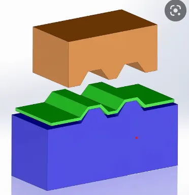
Basic Embossing Process
An Embossing is created by pressing a female Die into a male Counterforce with the substrate to be embossed between the two. The Die and its matching Counterforce are aligned in registration and the substrate is positioned so that it is located in registration (the correct position). Then the Die and its Counterforce are brought together under huge pressure, distorting the substrate and forcing it to conform to the contours of the Die. The resulting sculptured effect on the substrate adds a new dimension to it.
Detail Process of Embossing:
The metal sheet embossing operation is commonly accomplished with a combination of heat and pressure on the sheet metal, depending on what type of embossing is required. Theoretically, with any of these procedures, the metal thickness is changed in its composition.
The metal sheet is drawn through the male and female roller dies, producing a pattern or design on the metal sheet. Depending on the roller dies used, different patterns can be produced on the metal sheet. The pressure and a combination of heat actually "irons" while raising the level of the image higher than the substrate to make it smooth. The term "impressing" refers to an image lowered into the surface of a material, in distinction to an image raised out of the surface of a material.
In most pressure embossing operation machines, the upper roll blocks are stationary, while the bottom roll blocks are movable. The pressure with which the bottom roll is raised is referred to as the tonnage capacity.
Embossing machines are generally sized to give 2 inches (5 cm) of strip clearance on each side of an engraved embossing roll. Many embossing machines are custom-manufactured, so there are no industry standard widths. It is not uncommon to find embossing machines in operation producing patterns less than 6 inches (15 cm) wide all the way up to machines producing patterns 70 inches (180 cm) wide or more.
# Please Find the Attached Zip File for the Hood Assembly Design by using NX CAD.