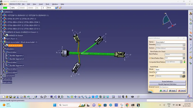
Wiring harness design in CATIA V5 - 3D modeling Week 5 & 6 Challenge
Q1. Route the following harness layout in Electrical workbench. Make assumption for harness bundle diameters. Use the connectors provided. After completion of routing,
- Check the bundle Continuity. Add snap of result in submission
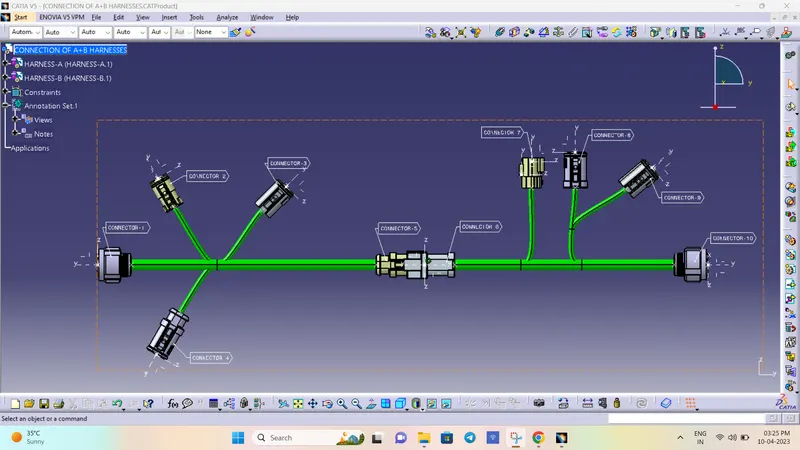
- Add annotation to all connectors. Make an assumptions for annotations like connect 1 , 2 etc
- Check for the bundle warning. Add snap.
- Generate CAT.part of harness assembly and convert is in. igs format.
Answer:
HARNESS-B
CONNECTOR-1:
- Create midpoint on the contact face which will be normal to wire bunddle insertion.
- Craete Axis System with respect to the point which we have created and defining the axis direction as shown below.
Switch to 'Electric Part Design'
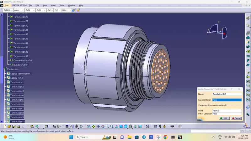
- Define the part as connector in catia, give no. of termination as 37 because we have 37 entry points for wire.
- Bundle connection point:
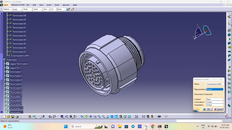
- Connector connection point:
CONNECTOR-2:
- Create midpoint on the contact face which will be normal to wire bunddle insertion.
- Craete Axis System with respect to the point which we have created and defining the axis direction as shown below.
Switch to 'Electric Part Design'
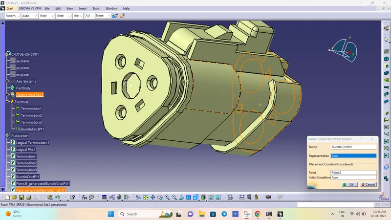
- Define the part as connector in catia, give no. of termination as 3 because we have 3 entry points for wire.
- Bundle connection point:
- Connector connection point:
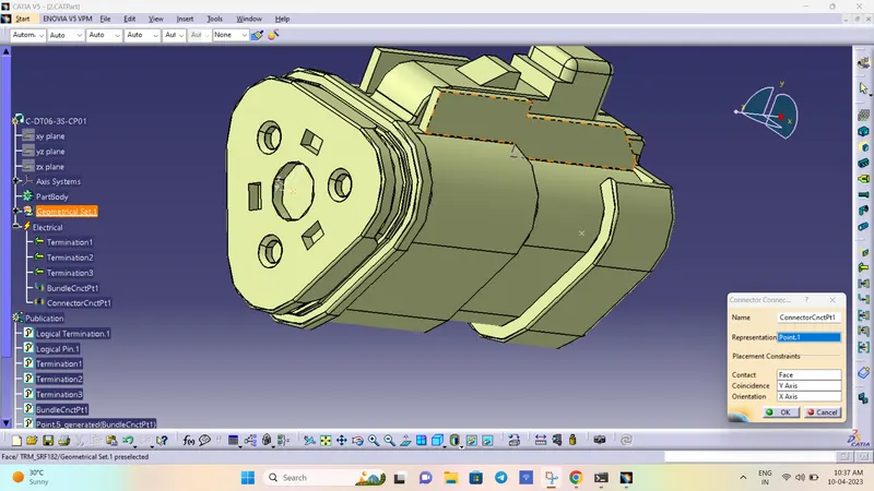
CONNECTOR-3:
- Create midpoint on the contact face which will be normal to wire bunddle insertion.
- Craete Axis System with respect to the point which we have created and defining the axis direction as shown below.
Switch to 'Electric Part Design'
- Define the part as connector in catia, give no. of termination as 8 because we have 8 entry points for wire.
- Bundle connection point:
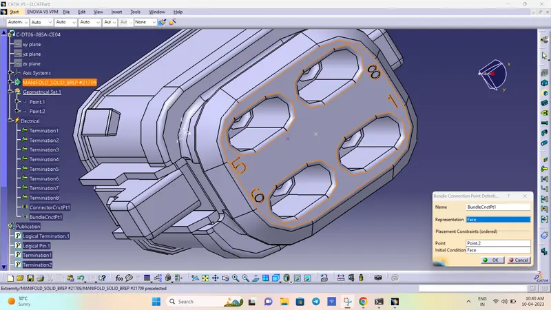
- Connector connection point:
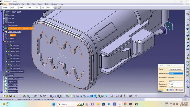
CONNECTOR-4:
- Create midpoint on the contact face which will be normal to wire bunddle insertion.
- Craete Axis System with respect to the point which we have created and defining the axis direction as shown below.
Switch to 'Electric Part Design'
- Define the part as connector in catia, give no. of termination as 8 because we have 8 entry points for wire.
- Bundle connection point:
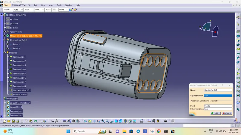
- Connector connection point:
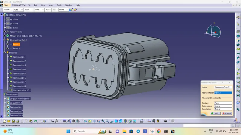
CONNECTOR-5:
- Create midpoint on the contact face which will be normal to wire bunddle insertion.
- Craete Axis System with respect to the point which we have created and defining the axis direction as shown below.
Switch to 'Electric Part Design'
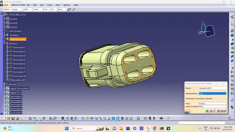
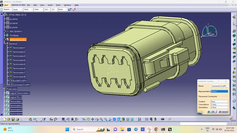
- Define the part as connector in catia, give no. of termination as 8 because we have 8 entry points for wire.
- Bundle connection point:
- Connector connection point:
HARNESS-B
CONNECTOR-6:
- Create midpoint on the contact face which will be normal to wire bunddle insertion.
- Craete Axis System with respect to the point which we have created and defining the axis direction as shown below.
Switch to 'Electric Part Design'
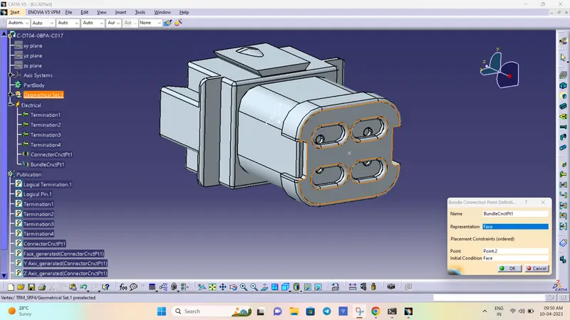
- Define the part as connector in catia, give no. of termination as 4 because we have 4 entry points for wire.
- Bundle connection point:
- Connector connection point:
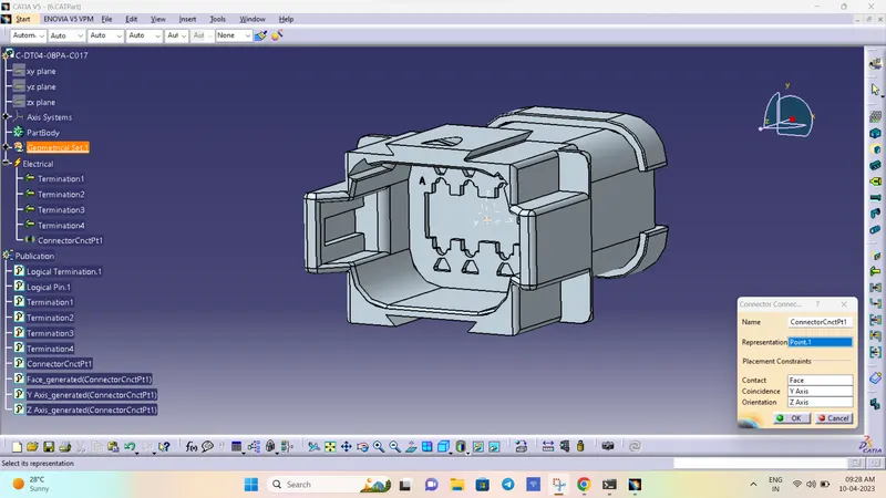
CONNECTOR-7:
- Create midpoint on the contact face which will be normal to wire bunddle insertion.
- Craete Axis System with respect to the point which we have created and defining the axis direction as shown below.
Switch to 'Electric Part Design'
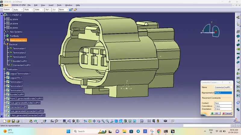
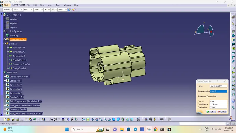
- Define the part as connector in catia, give no. of termination as 3 because we have 3 entry points for wire.
- Bundle connection point:
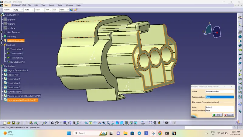
- Connector connection point:
- Connector CAVITY point:
CONNECTOR-8:
- Create midpoint on the contact face which will be normal to wire bunddle insertion.
- Craete Axis System with respect to the point which we have created and defining the axis direction as shown below.
Switch to 'Electric Part Design'
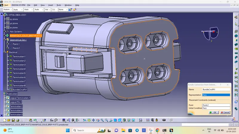
- Define the part as connector in catia, give no. of termination as 8 because we have 8 entry points for wire.
- Bundle connection point:
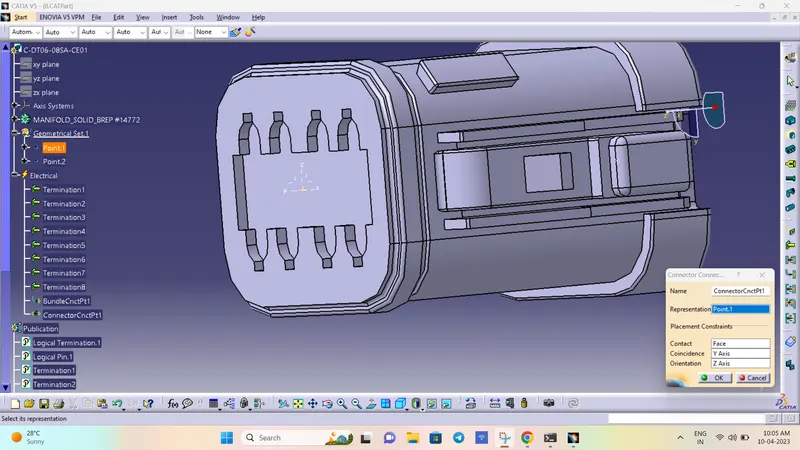
- Connector connection point:
CONNECTOR-9:
- Create midpoint on the contact face which will be normal to wire bunddle insertion.
- Craete Axis System with respect to the point which we have created and defining the axis direction as shown below.
Switch to 'Electric Part Design'
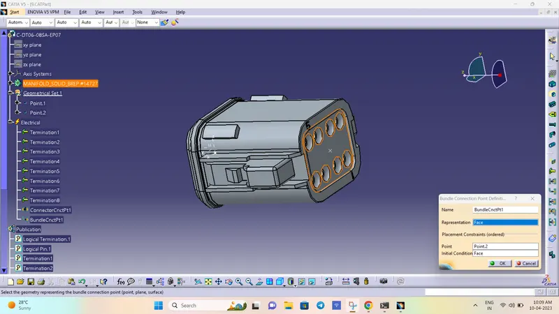
- Define the part as connector in catia, give no. of termination as 8 because we have 8 entry points for wire.
- Bundle connection point:
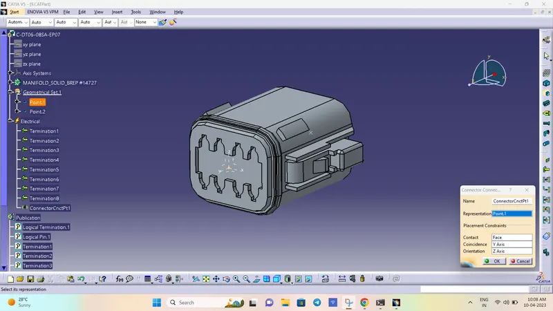
- Connector connection point:
CONNECTOR-10:
- Create midpoint on the contact face which will be normal to wire bunddle insertion.
- Craete Axis System with respect to the point which we have created and defining the axis direction as shown below.
Switch to 'Electric Part Design'
- Define the part as connector in catia, give no. of termination as 37 because we have 37 entry points for wire.
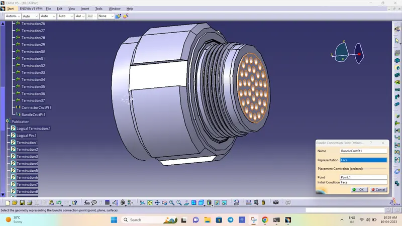
- Bundle connection point:
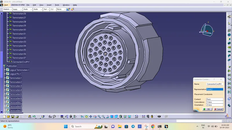
- Connector connection point:
HARNESS CONNECTIVITY CHECK
After all the connectors are defined, the workbench was switched to Electrical Harness Assembly where Geometrical Bundle was activated. All the connectors were routed using the Multi-Branchable Document command.
- Now in this step, we have to check bundle continuity in both Harness A and Harness B.
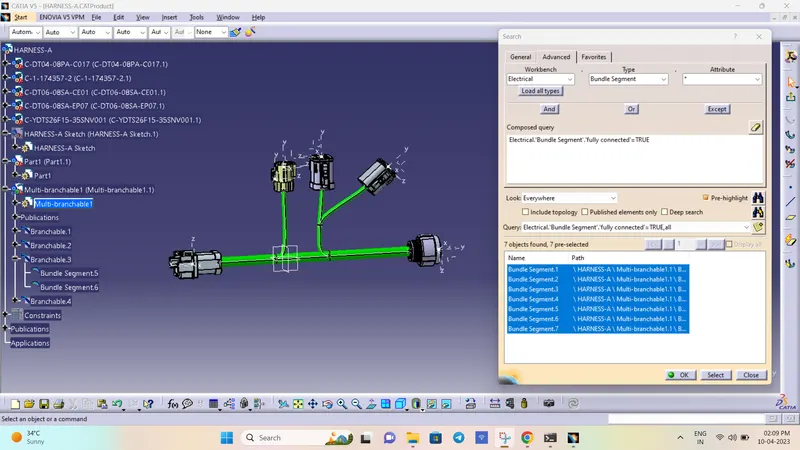
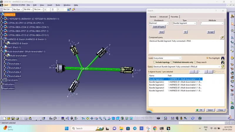
- So for that, go in Edit>Search>Workbench-Electrical>Type-Bundle segment>Attribute-fully connected.
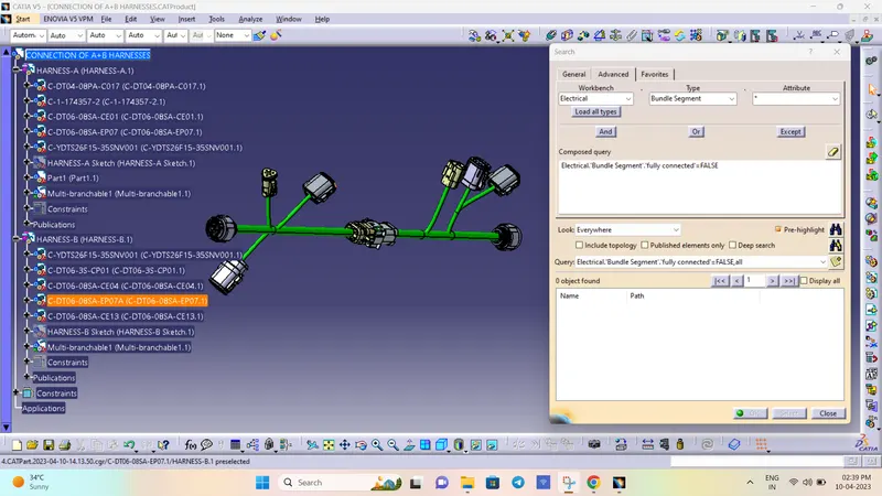
- We will get one window, in that selecting True option will show all the connected bundle segments while selecting False option will show all the non-connected bundle segments.
- Now, we will check for True condition and search for result.
- All the bundle segments are showing connected. So there is bundle continuity in both Harness A & Harness B as shown in below images.
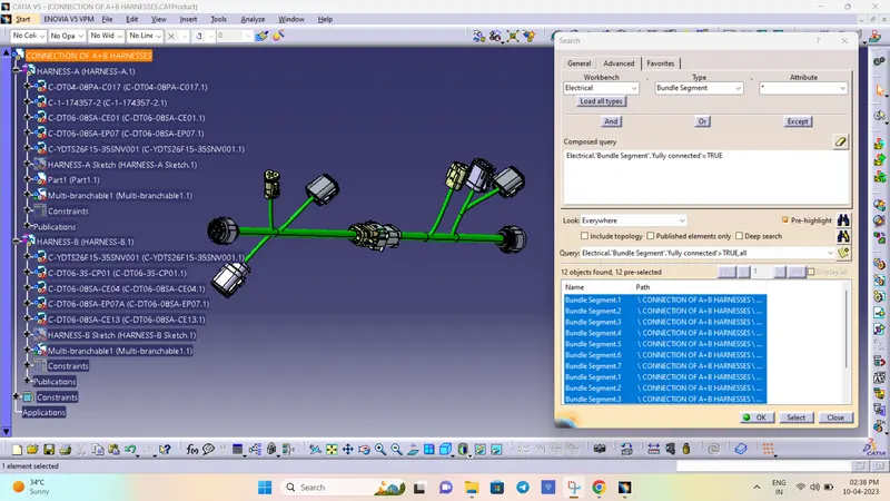
Checking for discontinuty
3D Annotation for all Connectors
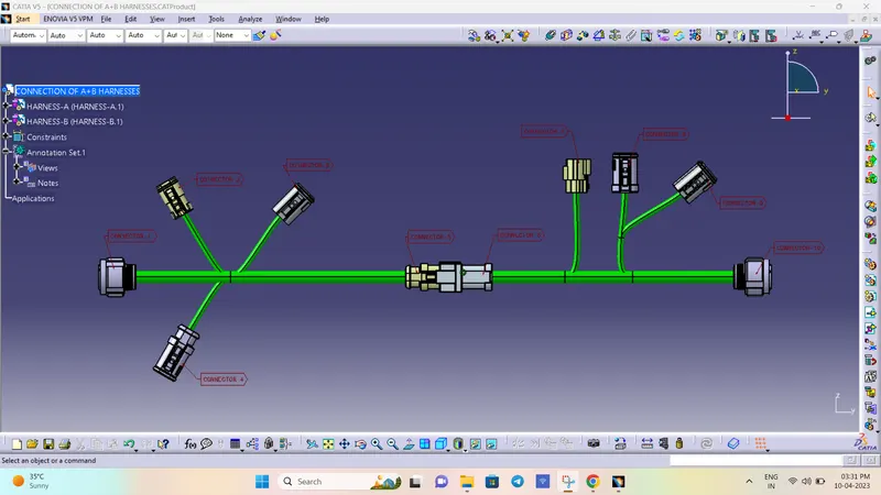
NOTE:
For some reason annotations are showing (?) error after saving the file. I have consulted with the TSE and tried different methods in group session he told me to submit as it is and mention it in the report. But after clicking the connector they are turning to white colour. My self and conserned TSE sir are not able to find the error.
Bundle warnings:
- Tangent error:
In this the direction of tangent is given in wrong direction. This can be rectified by changing the direction of the tangent or by clicking reverse tangent option at the required object.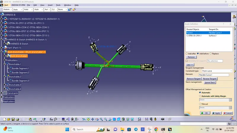
- Bend radius error
This problem can be solved in different ways:
- Can be rectified by giving required amount of slack value.
- can be rectified by changing the branching point.
- can be rectified by changing the position of connecor/ component.