Wiring harness design in CATIA V5 - 3D modeling Week 5 & 6 Challenge
REPORT :
1.Initially for the individual part files first take the files in the part file and then define the parts electrically.The component can be defined electrically by
1.Define the connector point
2.Define the axis system
3.Define the connector
4.Define the bundle connection point
All the above points are need to be defined for the overall components of the harness system.
2.Next import the 1 to 5 components in the harness B by using the option has existing component
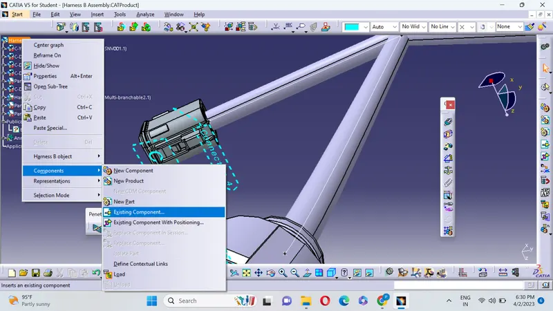
And Assume the respective lengths from each components and connect the components by the bundle connection (to do bundle connection first the component need to be geometrically defined).
3.Now follow the same procedure for the harness A and define the wiring harness has given in the question.
Smart Move:
For using smart move option first the object to be moved should be selected so that it does not effect the harness parts.
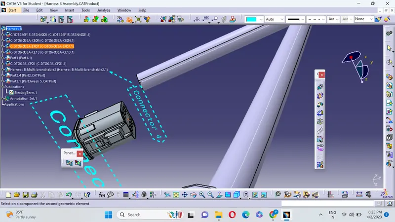
HARNESS A :
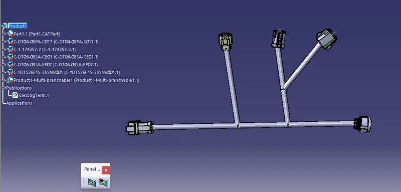
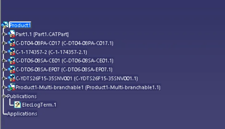
HARNESS B :
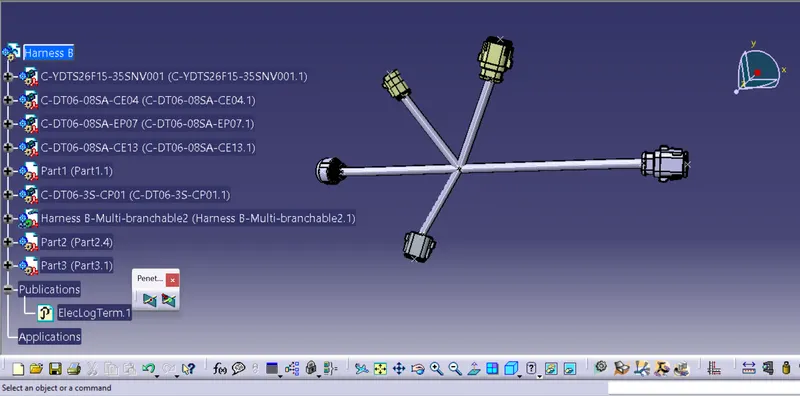
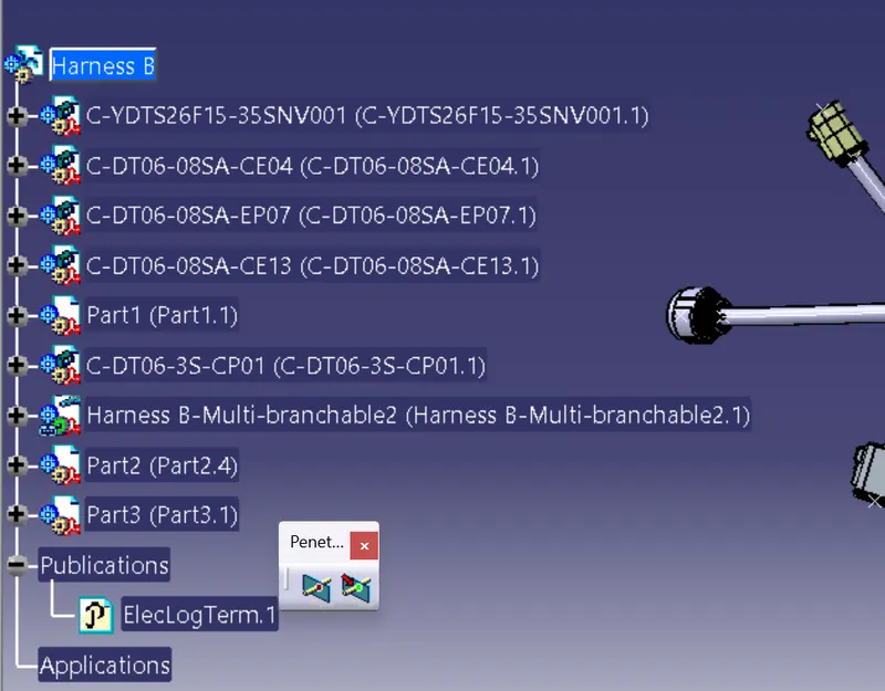
Labellings are also given for the harness
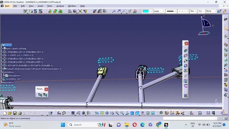
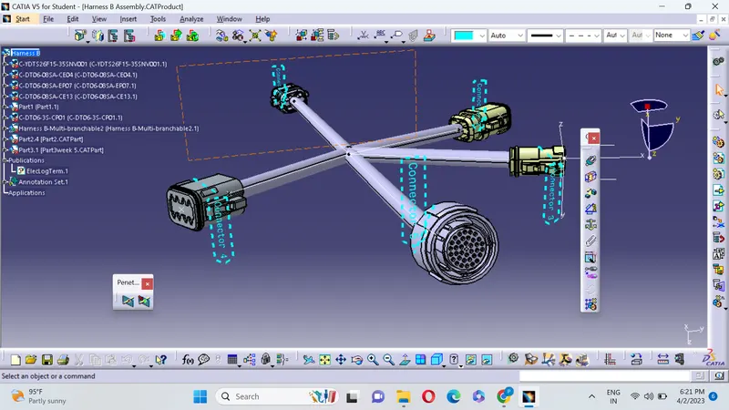
4.Now take the new product file and insert the harness A and Harness B into the new file and arrange the componet 5 and component 6 near by using connect electrically option the 2 components are connected together.
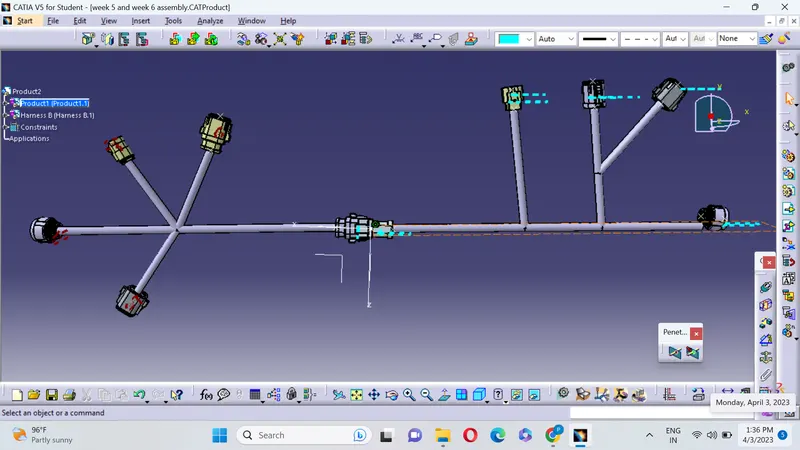
This the final harness design of the harness A and harness B
CONCLUSION :Therefore all the given statements are satisfied and harness designes are given