Wiring harness design in CATIA V5 - 3D modeling Week 5 & 6 Challenge
Wiring harness design in CATIA V5 - 3D modeling Week 5 & 6 Challenge
Solution:
- All the Connectors are downloaded from Google Drive link by skill lync
- We have downloaded all the igs zip files
- All the files are extracted
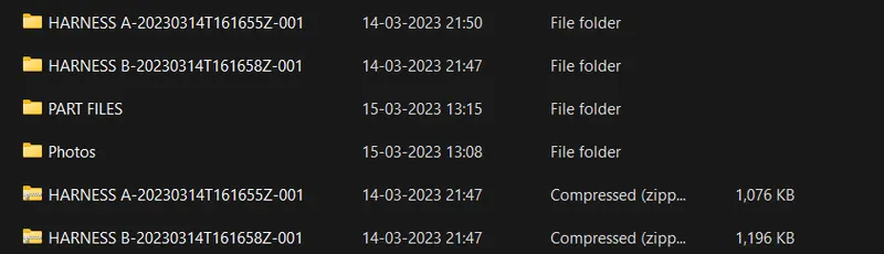
- Open the CATIA software and convert the files to CAT parts
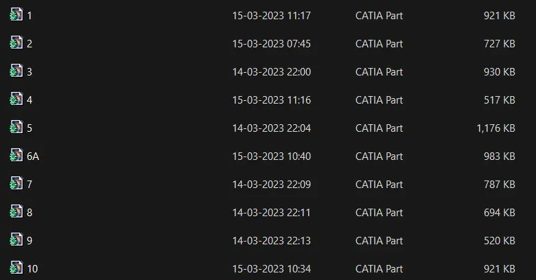
- All the Connectors are electricaly defined with the below steps
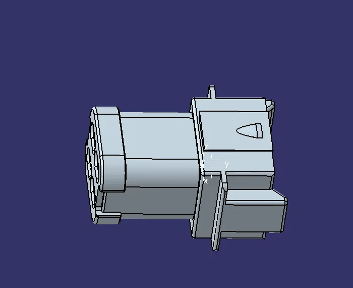
- Part body is opened and points are created for bundle entry
- Mating points are also created along with the axis definition
- we then switch to electrical part design
- We define the parts as connectors
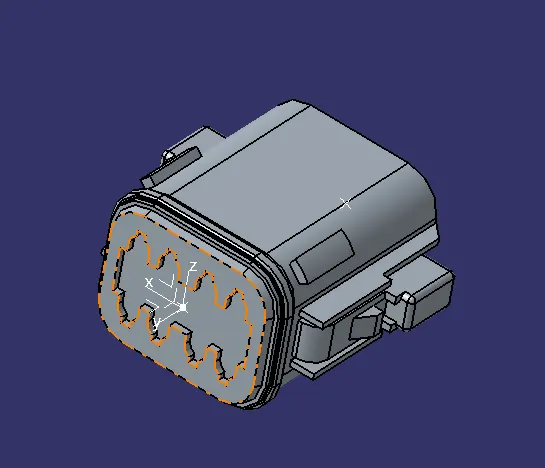
- We define the point and budle entry point
- Connection connector point is also made.
- This is done for all the ten connectors.
- Hence it is electricaly defined.
- We then create a catalog for this challenge and all the connectors.
- Here are few photos of the steps.
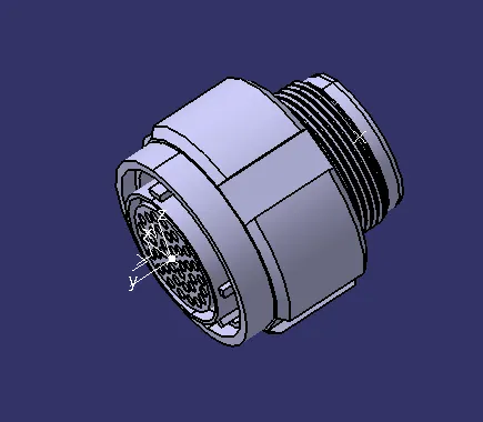
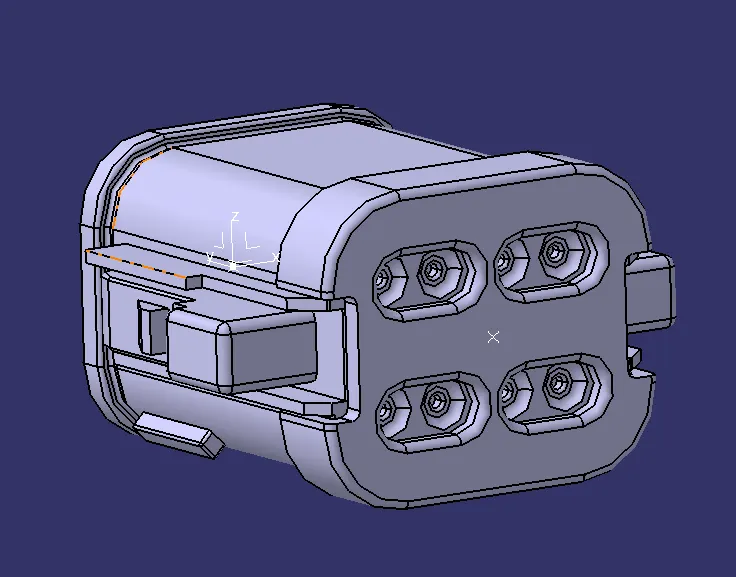
- New product is opened and it is named as Harness A and Harness B
- It is defined as geomentric bundle. Note the symbol has changed now.


- We add all the connectors here
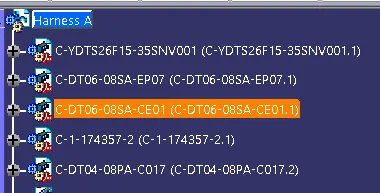
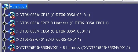
- The connectors are aligned as per the photo given.
- We use various commands to rotate and move the connectors
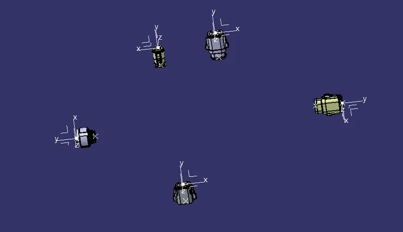
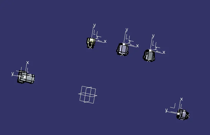
- Multi branchable is added to the geomentrical bundle
- Connectors are routed with the branch bundle by clicking the connectors
- To add sub branches Branch point is created on the main line.
- Then branches are routed to the connectors as per the question
- Tangency are changed to give a good curvature to the harness bundle
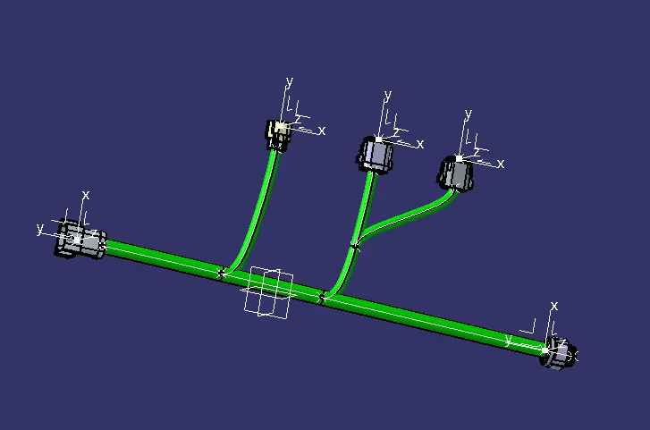
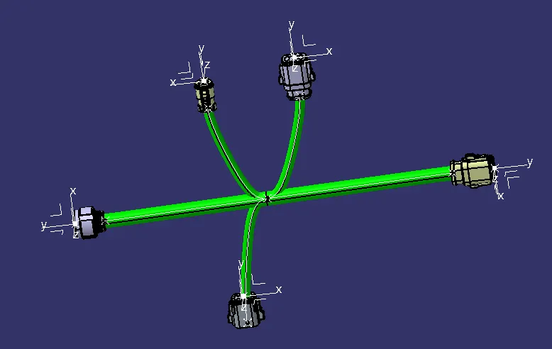
Problems and solutions in bundle routing warning:
- Have tangency so that the wire travels minimum distance
- So here we can change the reverse tangency to correct this
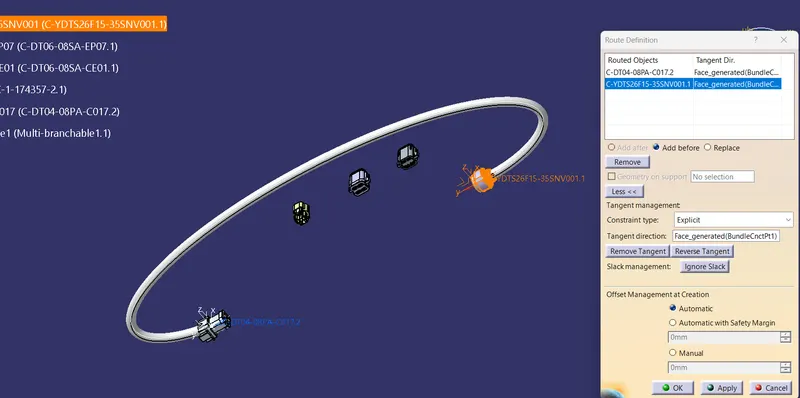
- This also a miss align of bundle that is shown in red line
- We can change the tangency of second connector to correct this issue
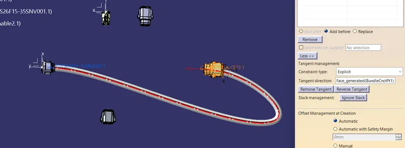
- We will get this kind of red line mentioning as error.
- For this we have multiple solution.
- we can increase the slack
- we can reverse the tangency
- we can move the connector location
- But here we have reversed the tangency to get the problem resolve
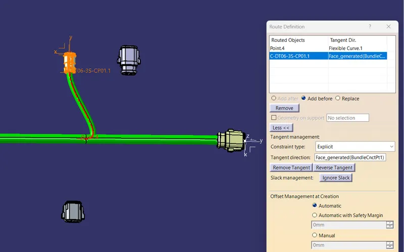
- Sometimes given high slack also makes problem
- So we kept minimal or 0 slack
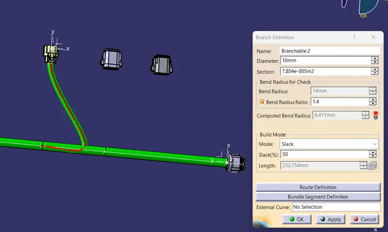
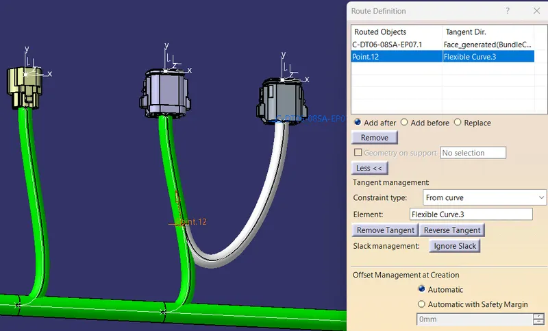
- Keep the branch points bit away so that the branch has a good curvature
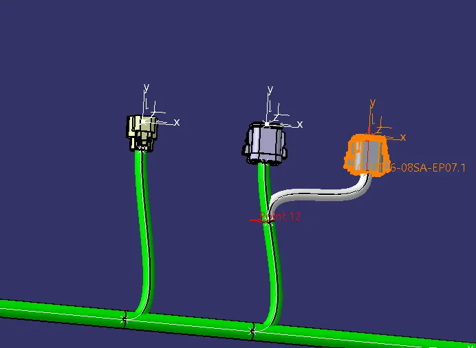
- We will get this kind of red line mentioning as error.
- For this we have multiple solution.
- we can increase the slack
- we can reverse the tangency
- we can move the connector location
- But here we have reversed the tangency to get the problem resolve
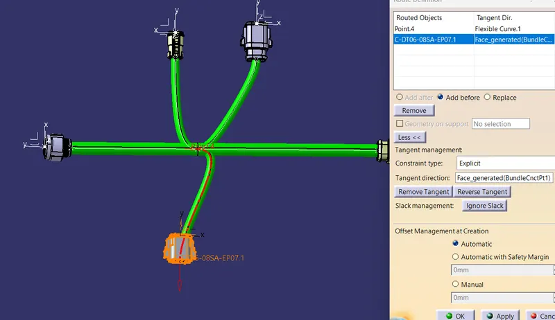
- Keep a good minimal cure of bundle to reach the connector
Assembly:
- New product is created and Harness A and Haness B is added
- Both the harness are joined with link
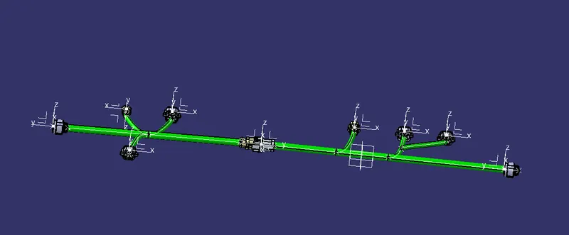
Annotations:
- Annotations are given to all the connectors
- Part assembly design is used here
- plane is created and names are added
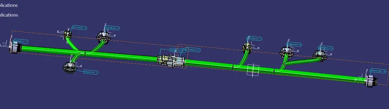
Bundle continuity:
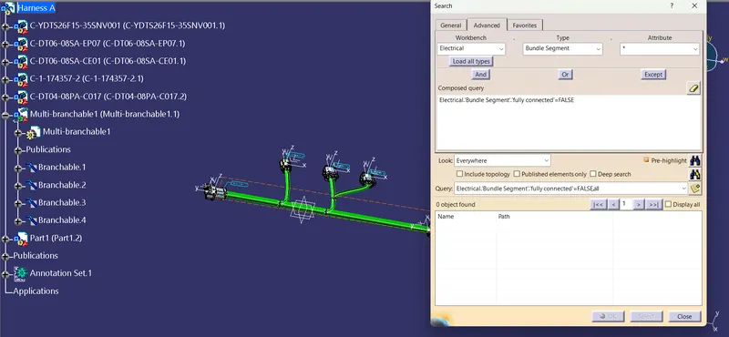
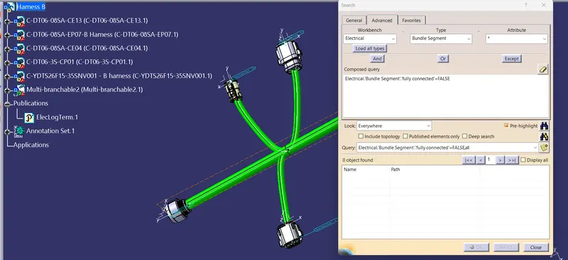
- Bundle continuty is checked by clicking search and electrical and bundle segment and fully connected
- here are the results
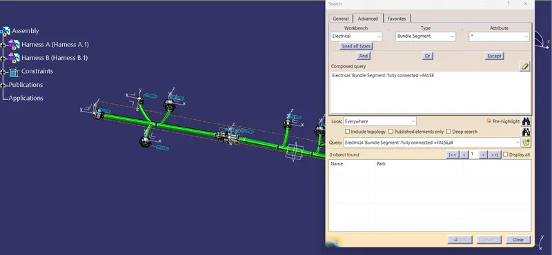
Assembly is saved as igs format in the attachement