Wiring harness design in CATIA V5 - 3D modeling Week 5 & 6 Challenge
OBJECTIVES:
- Define the mechanical components electrically and prepare the catalogue for the same
- Check the bundle is continous and the annotations are added for all the components in the assembly
- prepare the interconnection for harness A and B
- check for any bundle warnings and suggest what changes are made . also create Catpart from the assembly by using convert catproduct to catpart option
- Prepare a report with all the required images required for the challenges .
- attach all the necessary Catpart files and Catalogue files and assembly files
Answer:
Define the mechanical connectors Electrically:
- First step is to create the parameters of the all mechanical connectors using mechanical part workbench.
- Next step is to create bundle connection point and create connector connection point.
- Then create connector connection axis, where Y axis facing towards connector entry and X axis toward locking mechanism.
- Then define the connectors electrically using electrical part workbench.
- First step is define the connector and terminals using connector option.
- Then Define bundle connection point option to define bundle entry position.
- Then Define connector connection point option to define connector entry point.
- Then add all the connectors in the catalog
Creation of Harness A & B Assembly:
- Initial step for creating bundle routing is arranging the connectors as per the layout location.
- Then add all the connectors in the geometrical bunde assembly file using existing file option or add using catalog browser option from part assembly workbench
- Then define the assembly by electrical using geometrical bundle option from electrical harness assembly workbench and select the assembly product file.
- Then put the connectors in the desired location using manipulation, snap and compass option from part assembly workbench
- After arranging the connectors in the desired location the next step is to create routing.
- For creating routing we have to select multi branchable document option from electrical harness assembly work bench.
- Then the multi branchable file is created, Then provide the appropriate bundles in the connector.
- Add branch point option to create branch points in the bundle.
- Then create annotations from part assembly workbench.
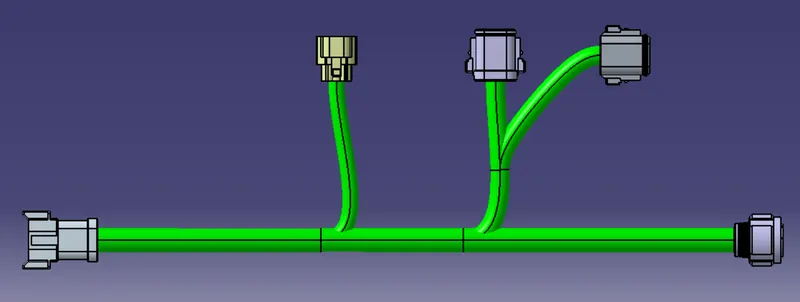
Fig: Harness A assy
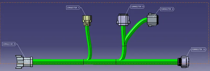
Fig: Harness A assy with annotation
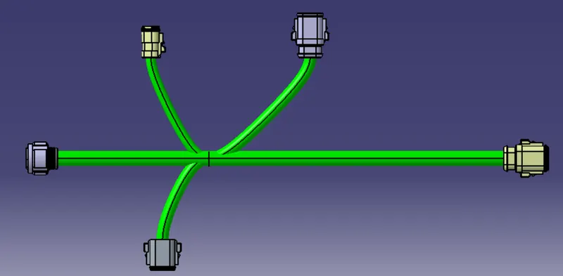
Fig: Harness B assy
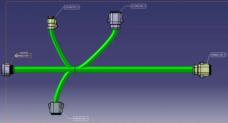
Fig: Harness A assy with annotation
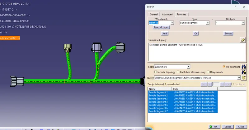
Fig: Harness A Bundle connectivity (True)
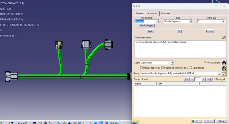
Fig: Harness A Bundle connectivity (False)
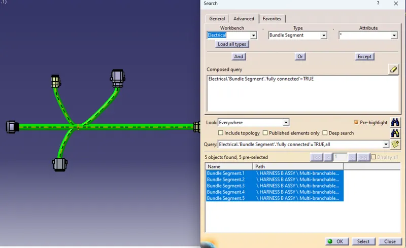
Fig: Harness B Bundle connectivity (True)
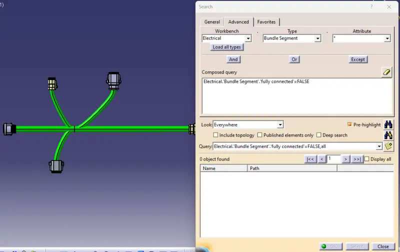
Fig: Harness B Bundle connectivity (False)
Interconnection of Harness A and B creation:
- Interconnection has been done from electrical assembly design workbench
- For that create new product file and added the harness A and B assy product files using existing components option
- Then Connect electrical options to interconnect the connector 5&6 together.
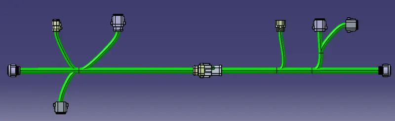
Fig: Interconnection for harness A and B
Conclusion:
Mechanical components are electrically defined using electrical part workbench and prepared the catalogue for the all connectors. Checked the bundle continous and the annotations are added for all the components in the assembly has been completed. Then prepared the interconnection for harness A and B. Then checked for any bundle warnings and there is no warnings and attached all the necessary Catpart files, igs file and Catalogue files and assembly files.