Wiring harness design in CATIA V5 - 3D modeling Week 5 & 6 Challenge
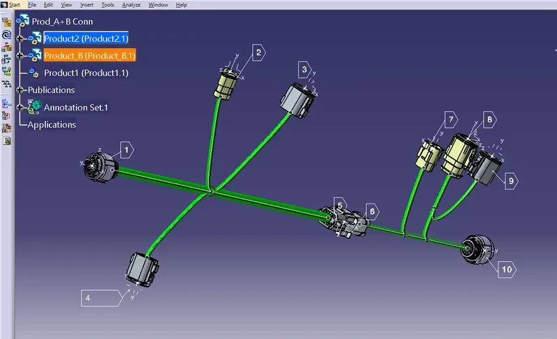
1. There are different types of connectors in ten different places.
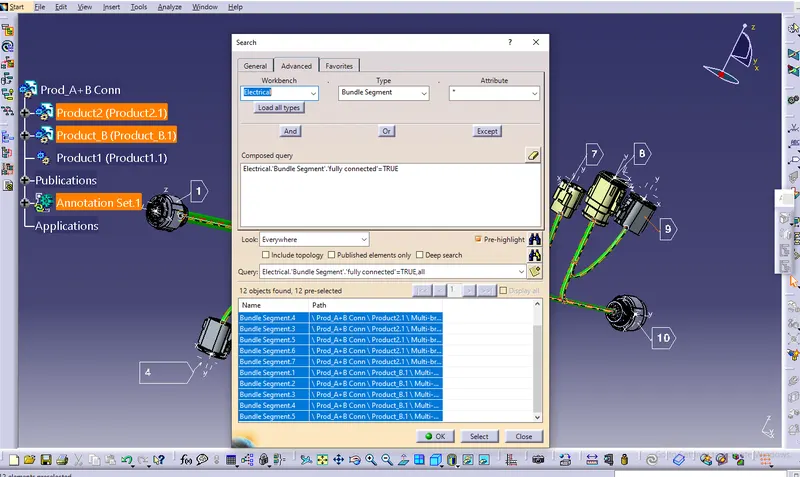
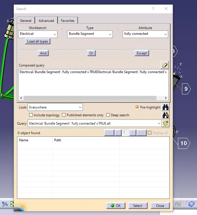
2. Bundle continuity for the two created harnesses must be checked.
3. Once the two Harnesses have been created, the next step is to connect them electrically.
4. Examine Harness A and Harness B for bundle warnings.
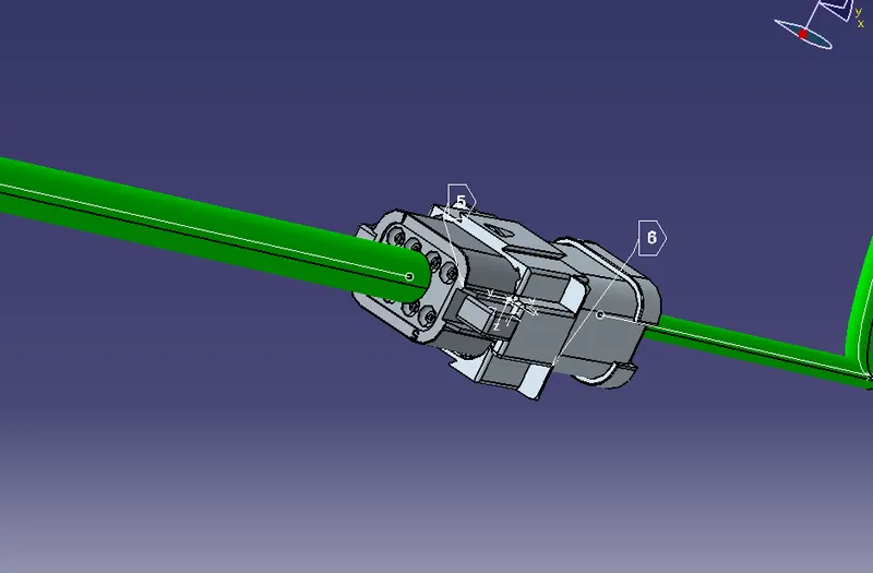
5. Annotate all of the connectors in Harness A and Harness B.
6. The project's final goal is to convert the final harness file into IGS file format.
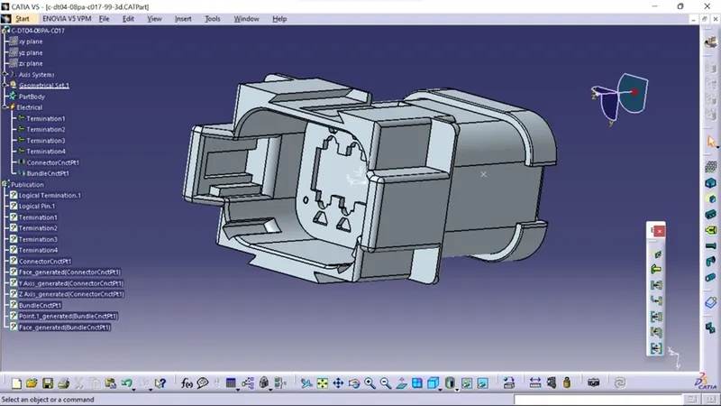
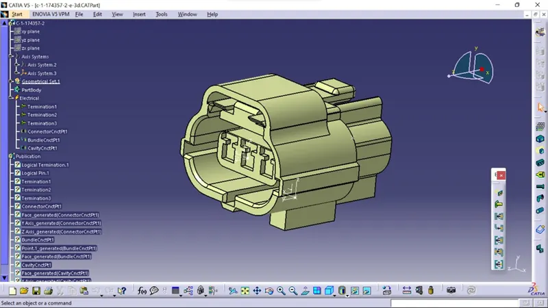
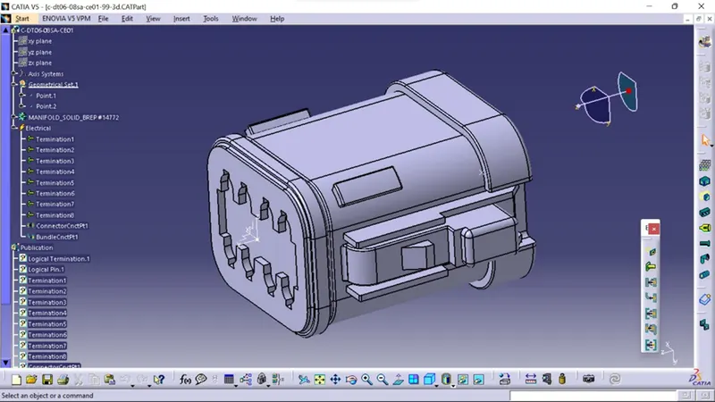
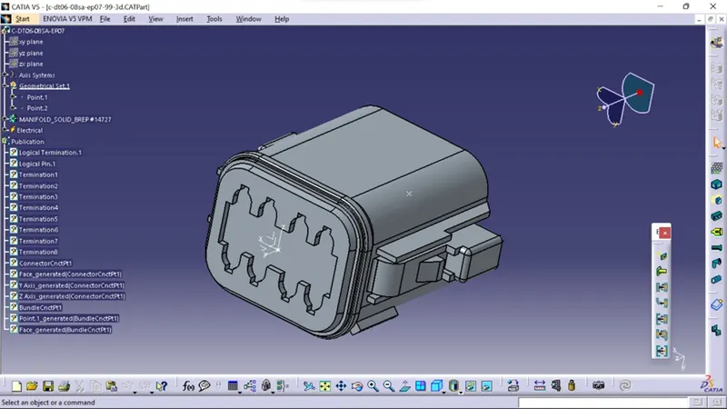
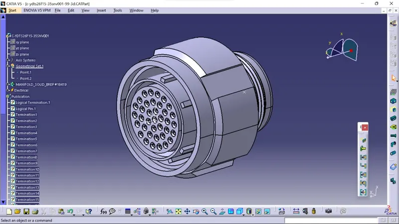
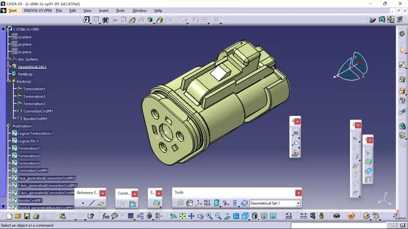
Create geometric and electrical definitions for all electrical connectors that will be used in the wiring harness.
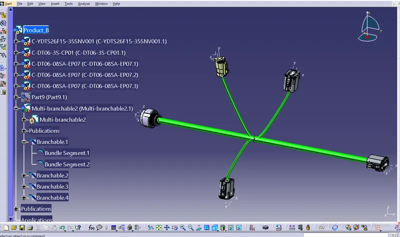
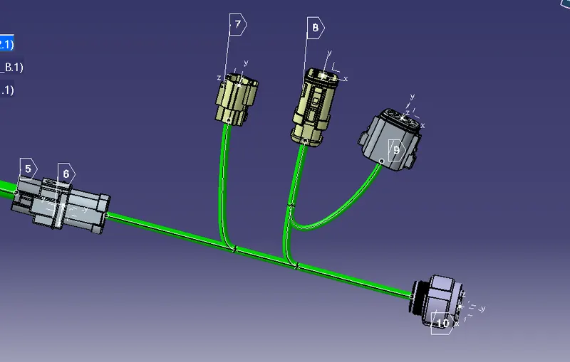
Using the electrical harness workbench in CATIA V5, create harness A and harness B as shown below.
First, all of the connectors are placed in their proper positions. Second, bundle segments with branch points and branches are created between the connectors, as shown below.