Wiring harness design in CATIA V5 - 3D modeling Week 5 & 6 Challenge
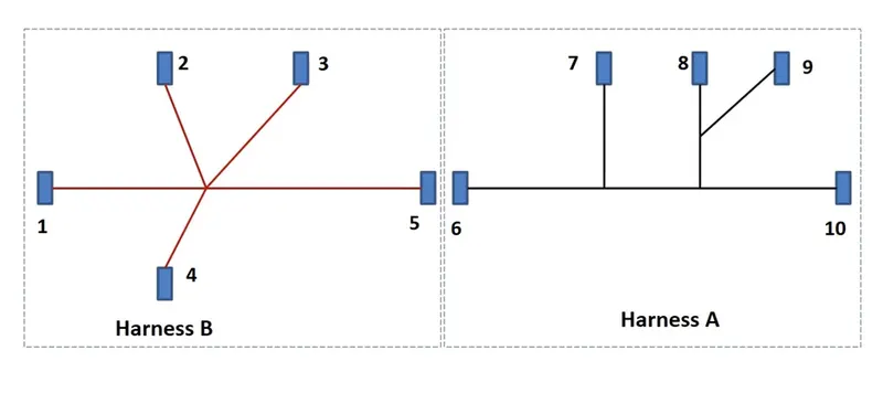
Q1. Route the following harness layout in Electrical workbench. Make assumption for harness bundle diameters. Use the connectors. Use the connectors provided. After completion of routing.
1. Check the bundle Continuity. Add snap of result in submission
2. add annotation to all connectors. Make an assumptions for annotations like connect 1,2 etc
3. Check for the bundle warning. Add snap.
4. Generate cat. part of harness assembly and convert is in. igs format.
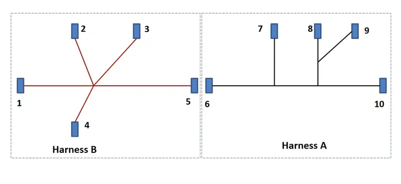
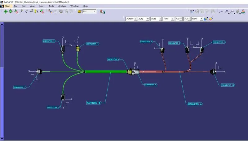
In the diagram above, the electrical connectors are represented by numbers.
1. There are different types of connectors in ten different places.
2. Bundle continuity for the two created harnesses must be checked.
3. Once the two Harnesses have been created, the next step is to connect them electrically.
4. Examine harness A and harness B for bundle warnings.
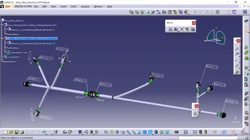
5. Annotate all of the connectors in harness A and harness B.
6. The projects final goal is to convert the final harness file into igs file format.
StEP1:
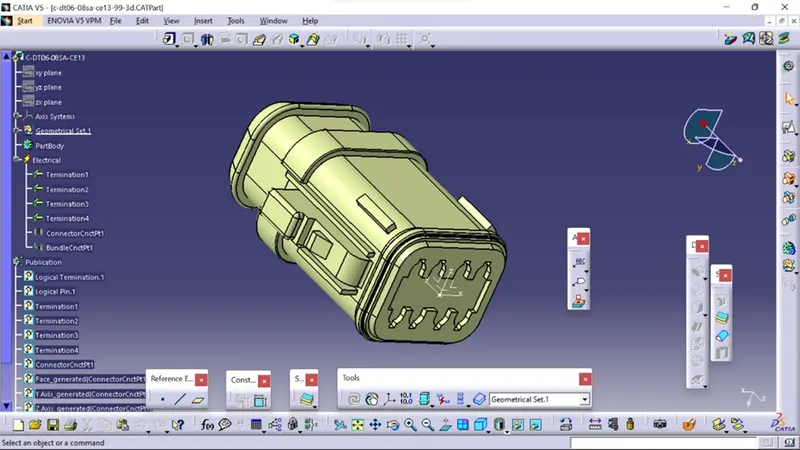
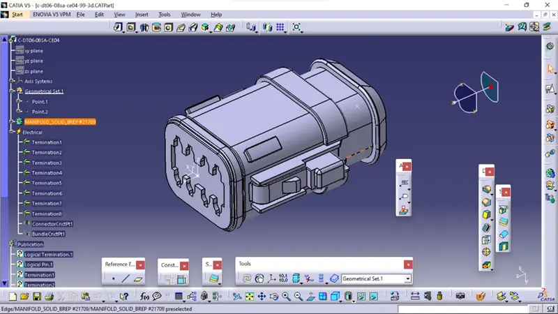
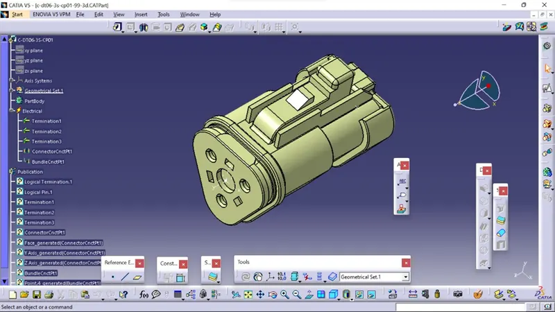
Creat geometric and electrical definitions for all electrical connectors that will be used in the wiring harness.
Connectors Used in Harness A
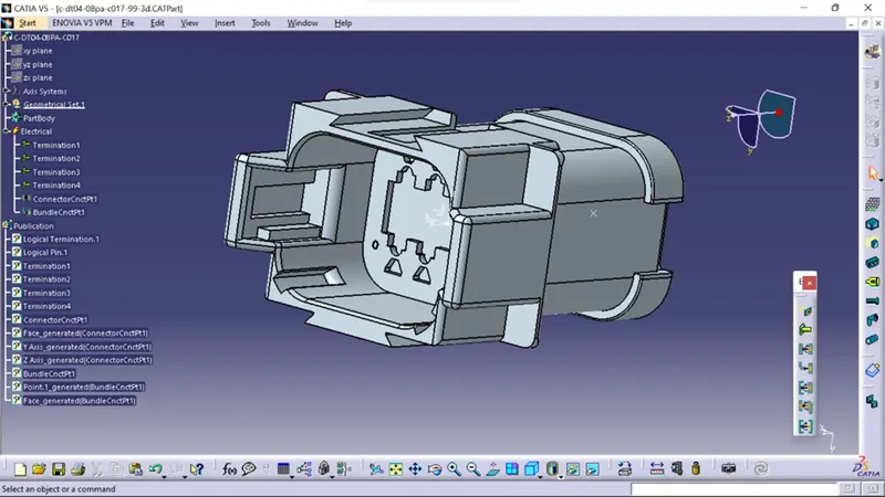
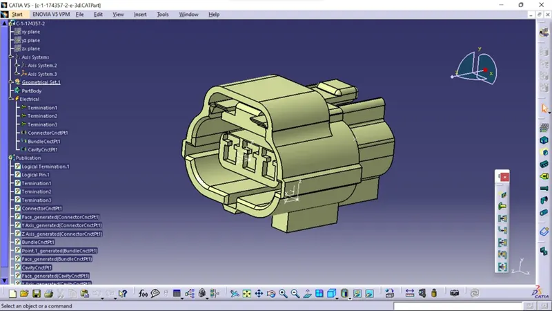
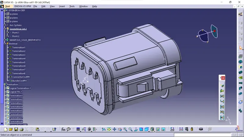
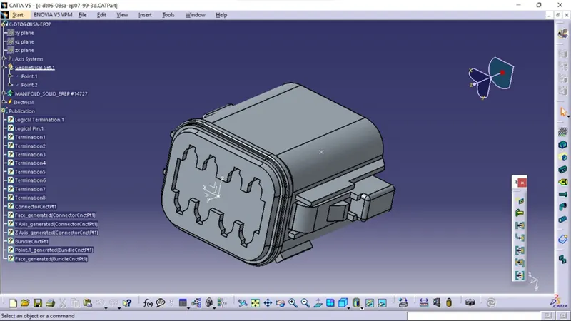
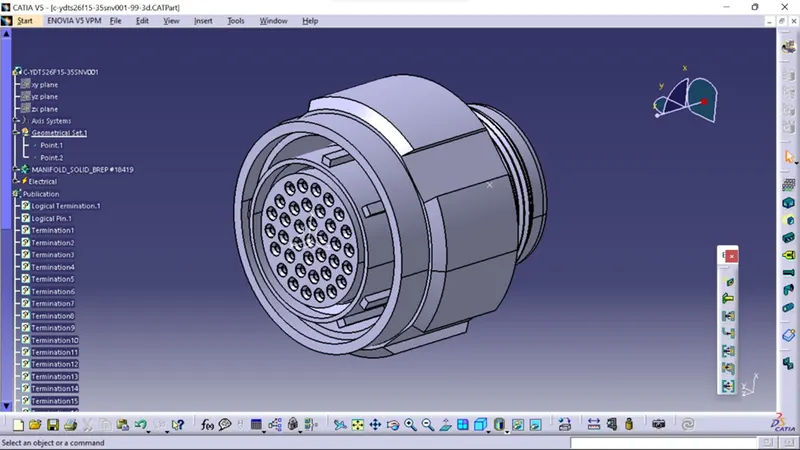
Connectors Used in Harness B
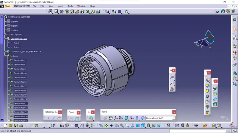
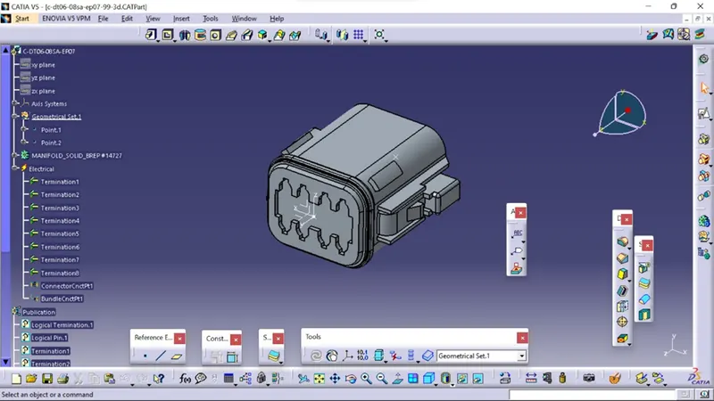
Step2:
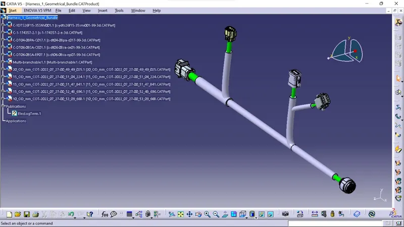
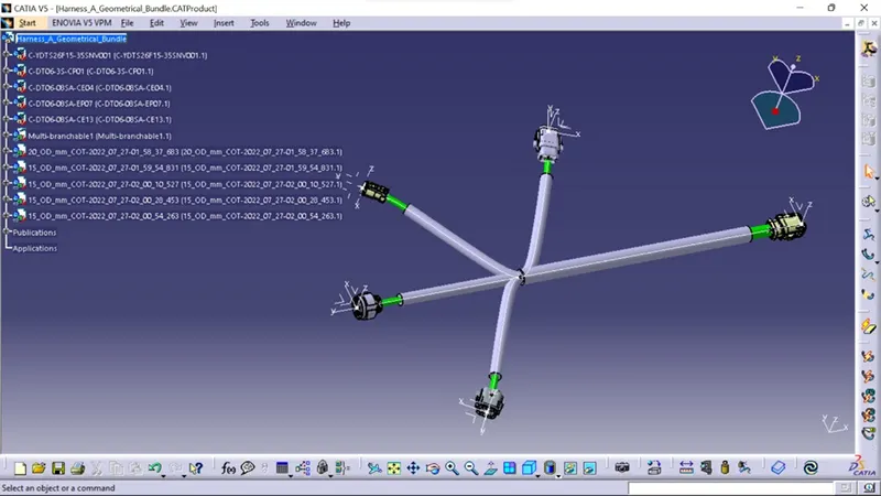
Using the electrical harness workbench in CATIA V5, create harness A and B as shown below.
First, all of the connectors are placed in their proper positions. Second, bundle segments with branch points and branches are created brtween the connectors, as shown below.
Bundle diameters of 15mm, 12mm, 8mm, and 5mm are assumed for various bundle segments. For all bundle segments, the bend ratio is 1.4 and the slack is zero percent.
Harness A
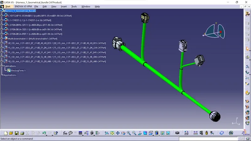
With Safety Corrugated tubes keeping ends 30mm away from the Connectors.
Harness B
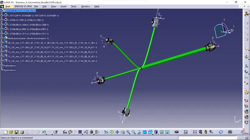
With Safety Corrugated tubes keeping ends 30mm away from the Connectors
STEP3:
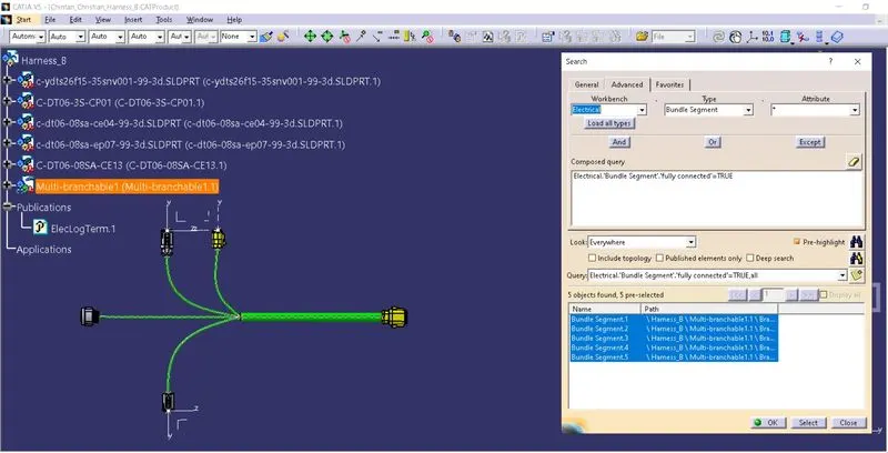
Following the creation of Harness A and Harness B, the bundle continuity must be checked.
To begin, ensure that multi-branchable is selected, then navigate to edit>Search>Advanced> Electrical Workbench> Type-Bundle Segment>Attribute-Fully Connected.
Selecting TRUE will display all connected bundle segments, while selecting FALSE will display all non-connected bundle segments.
STEP4:
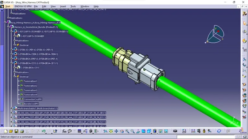
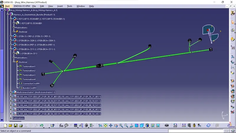
In this step, we must electrically connect Wiring Harness A and Harness B. A few steps must be taken in order to electrically connect the two harnesses.
To begin, create a new product file in CATIA and rename it Assy Wire Harness.
Second, insert harness Aand harness B into the newly created product file to create the final harness assembly.
Once inside the electrical assembly design workbench, connect the male and female connectors as shown below.
STEP5:
In this step, we will look for bundle warnings in HarnessA and B.
Geometrical bundle warnings for Bend radiuis, Bundle diameter, and Vector position are displayed. If these values or inputs are incorrect, a yellow flash will a[[ear in the tree structure next to the problematic branchable.
Depending on the route of the bundle segment, we can fix problem by adding slack or changing the vector position of the segment point. In our case, there is no Error.
STEP6:
In this step, we will annotate all of the electrical connectors.
Annotations are used to display connector functions as well as extra information. They are defined in CATIA V5 Assembly design Workbench.
First, we must select a plane on which to place the annotation.
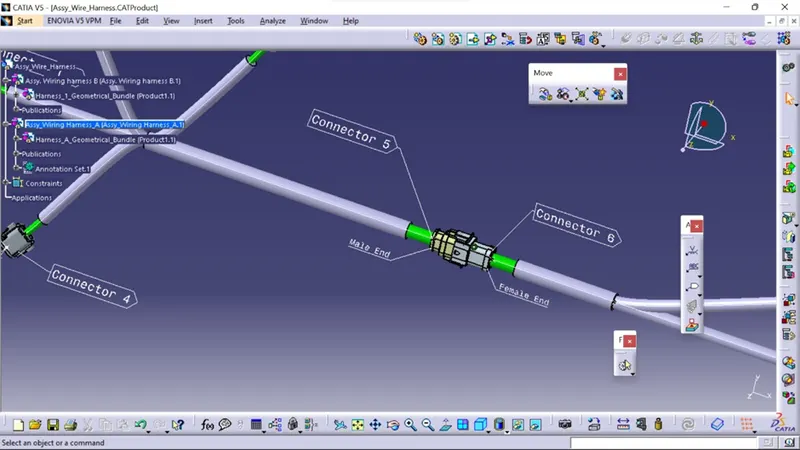
Second, select the flag note with ladder function and then individually click on connectors. As shown below, provide the necessary information to all of the connectors.
After we are added annotations to all of the connectors, we should increase the font size of the annotations to make them more visible.
STEP7:
The final step is to convert our Final Harness Assembly file into IGS format. To accomplish this, we must follow the steps outlined below.
Mechanical Assembly Workbench>Tools>Catalog Part Generation from Product
After creating the CAT part, the entire product file is converted into a single part. At this point, it is clear that all of the bundle segments are grey in color. So, we will go back and add green color to each bundle segment to match the Final Harness Assembly.
Finally, as shown below,we can use the SAVE AS feature to save the CAT part file as an IGS file.