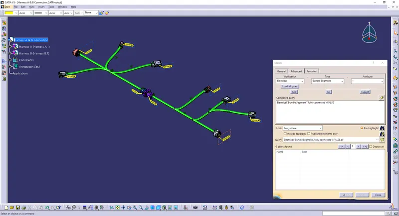
Wiring harness design in CATIA V5 - 3D modeling Week 5 & 6 Challenge
STEP 1 - To draw the given input blueprint layout in sketch
STEP 2 - Define all the required connectors
STEP 3 - Create a new assembly and insert the blueprint along with all the connectors
STEP 4 - Arranging all the connectors in it's respective places
STEP 5 - Defining it as geometrical bundle
STEP 6 - Start routing the branches along with sub branches
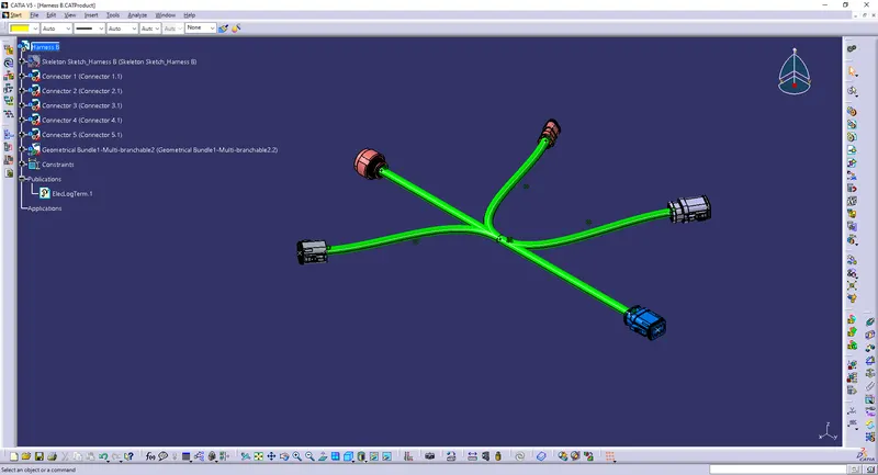
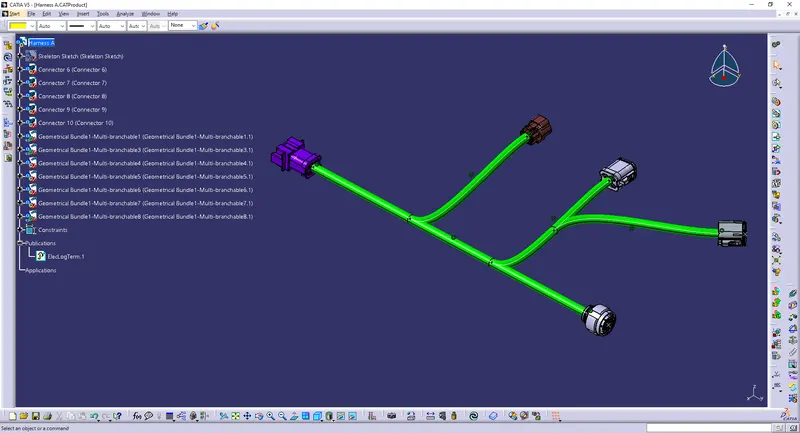
STEP 7 - Creating a new assembly by copying Harness A & B
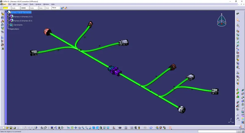
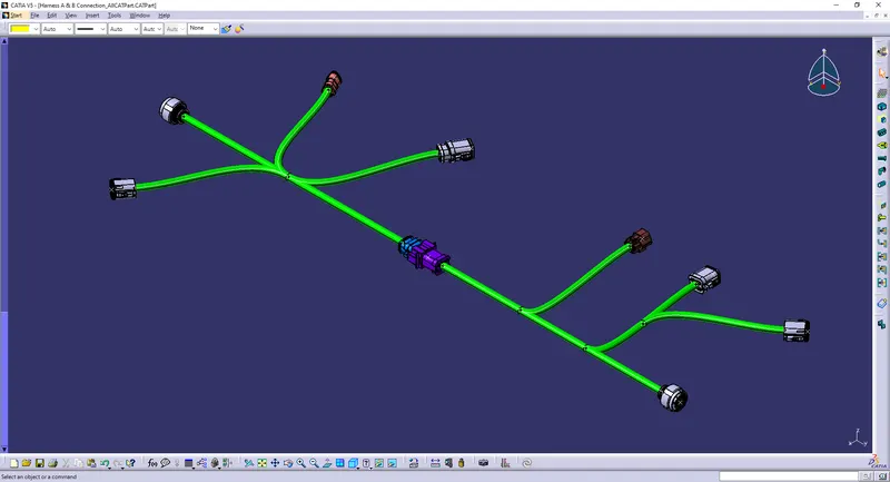
STEP 8 - Adding annotations for the connectors
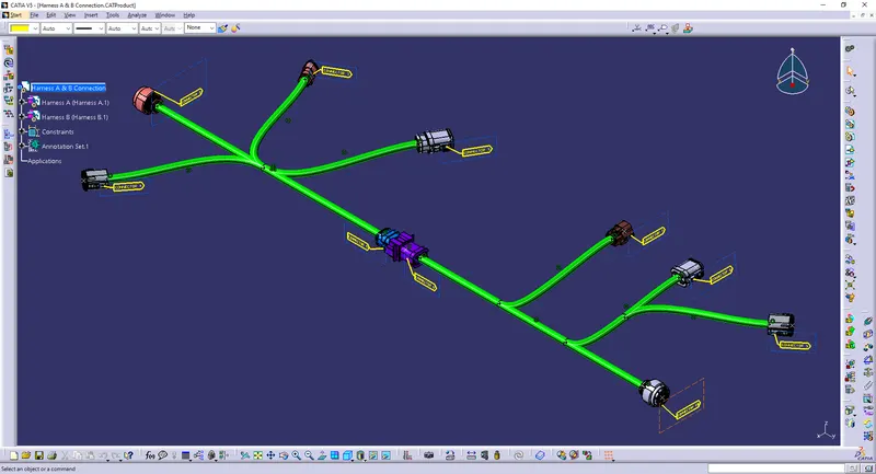
STEP 9 - Check for fully connected bundle segments