Wiring harness design in CATIA V5 - 3D modeling Week 5 & 6 Challenge
1)Aim :
- Check the bundle Continuity. Add snap of result in submission
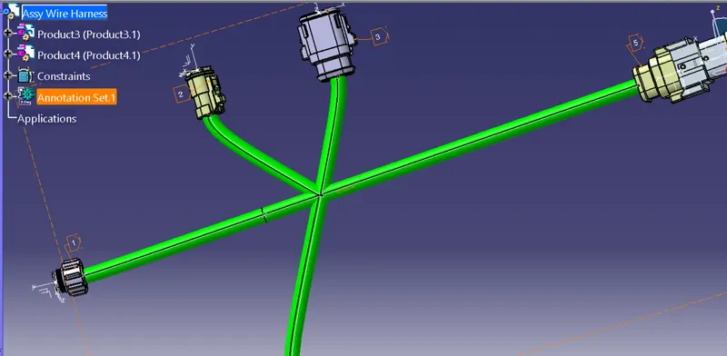
- Add annotation to all connectors. Make an assumptions for annotations like connect 1 , 2 etc
- Check for the bundle warning. Add snap.
- Generate CAT.part of harness assembly and convert is in. igs format.
Steps and procedures :
- The cad part was initially imported to the catia v5 software.
- The geometrical parameters like points and axis was set.
- The part was defined as electrical.
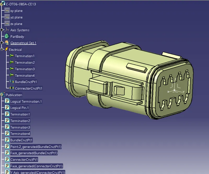
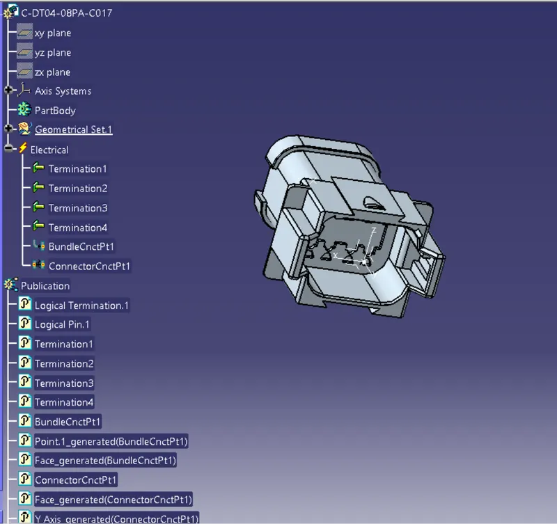
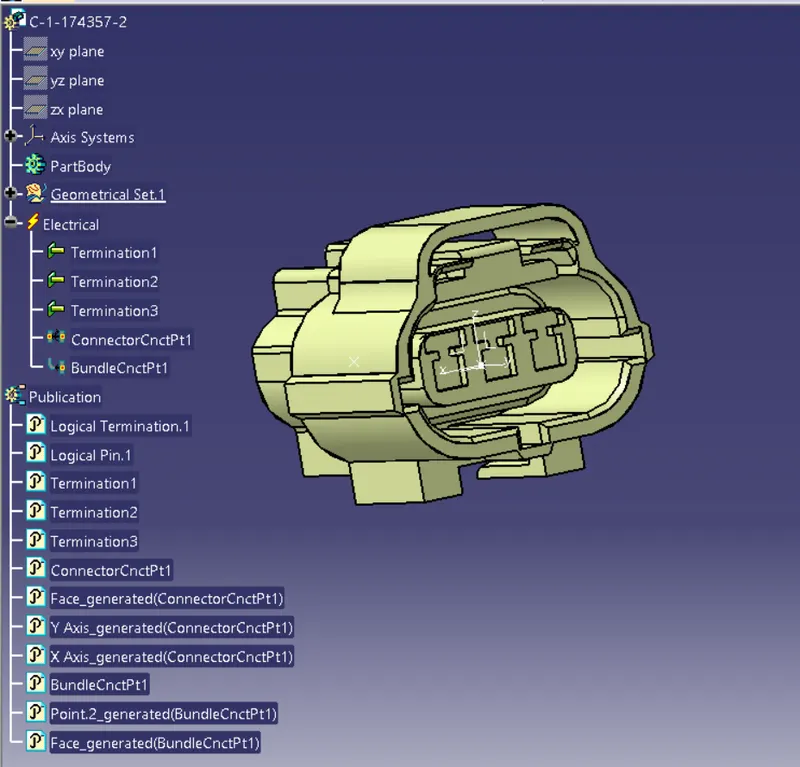
- The part was defined as a connector and the bundle connection point and the connector connection point was set.
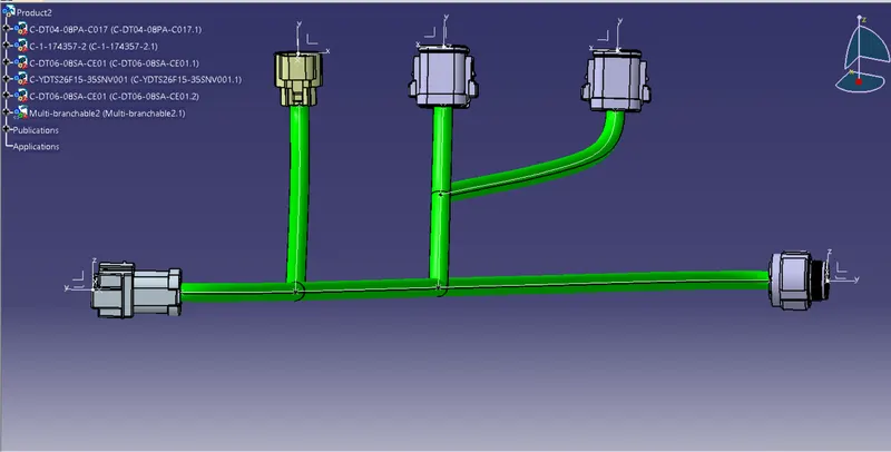
- The connectors was assembled in assembly workbench.
- The bundle connection was made according to the given diagram.
- Both the harness A and B was connected.
Harness B :
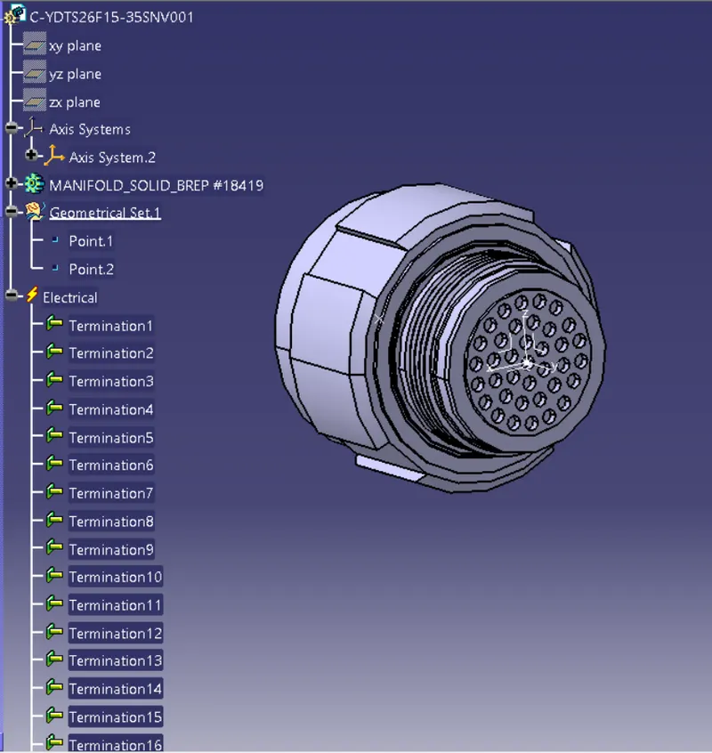
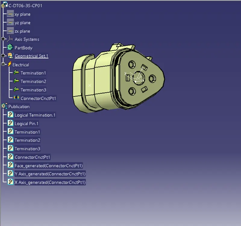
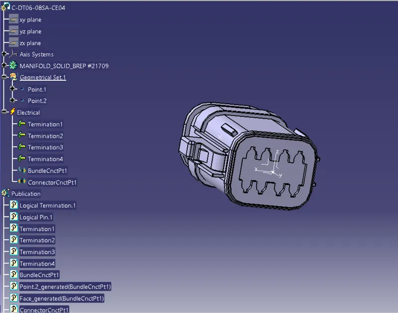
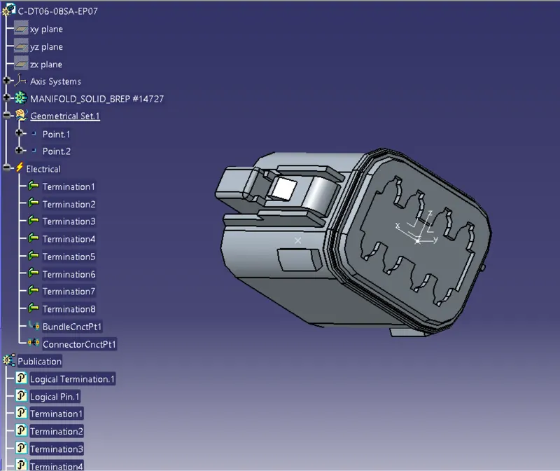
Harness B assembly :
Harness A :
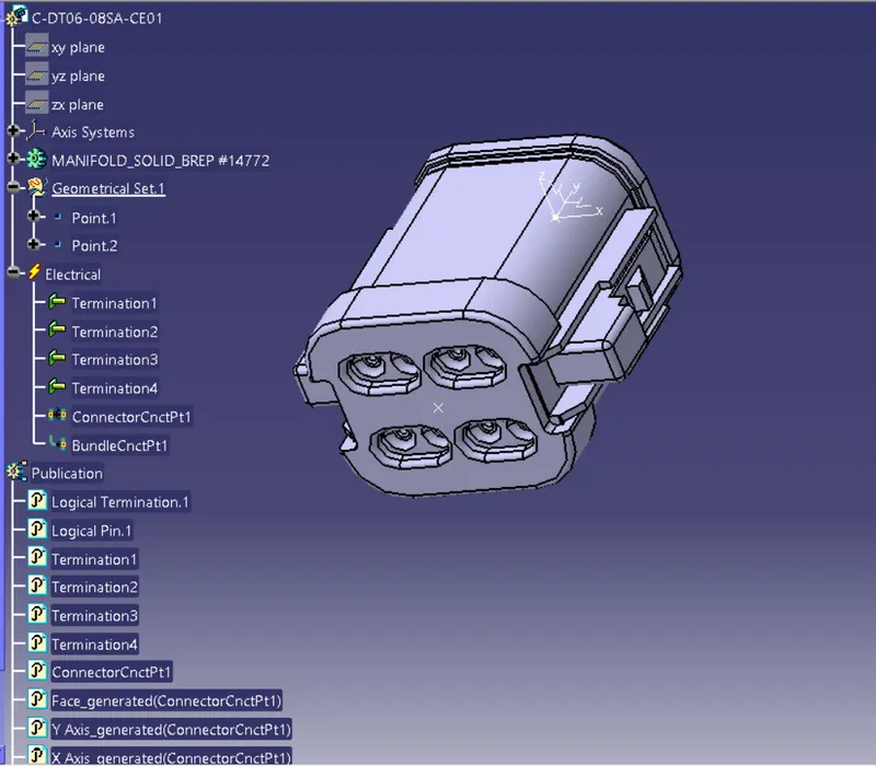
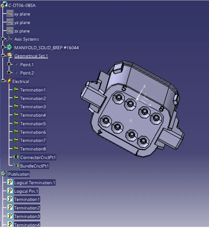
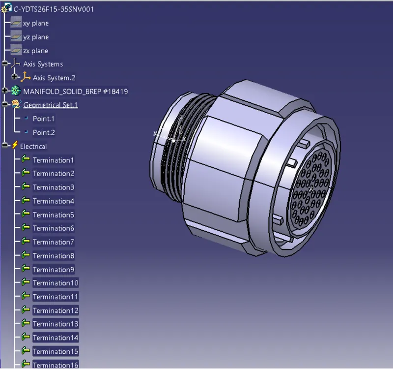
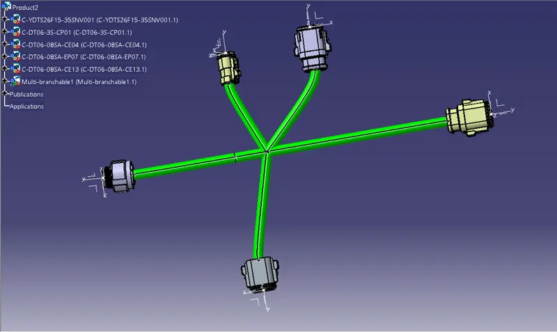
Harness A Assembly :
Joining Harness A ans Harness B :
- New product file should be opened.
- It should be renamed as Assy Wire Harness.
- Now the electrical harness discipline workbench must be opened.
- Both the harness A and B should be inserted here and connected using connect electrical device command.
Bundle Warnings :
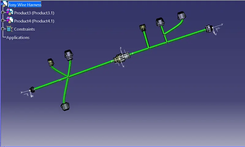
Geometrical bundle warnings for Bend radius, Bundle diameter, and Vector position are displayed. If these values or inputs are incorrect, a yellow flash will appear in the tree structure next to the problematic branchable. Depending on the route of the bundle segment, we can fix the problem by adding slack or changing the vector position of the segment point. In our case, there is no Error.
Annotation :
- To annotate we have to first open the assembly design workbench.
- Here we should first create a desired plane using view creation command and then annotate using flag note with leader command.
Converting the file to IGS format :
Mechanical Assembly Workbench>Tools>Catalog Part Generation from Product
After creating the CAT part, the entire product file is converted into a single part. At this point, it is clear that all of the bundle segments are grey in color. So, we'll go back and add green color to each bundle segment to match the Final Harness Assembly.
Finally, as shown below, we can use the "SAVE AS" feature to save the CAT part file as an IGS file.