Project - Speed Control of a Direct Current (DC) motor
SPEED CONTROL OF A DC MOTOR:
*Using kirchoffs voltage law one can derive
vs = Ra ia + La di/dt + vb
*Back EMF,angular velocity, and torque are related by
vb = Km D0/dt Toque = Kt i
*Here Km and Kt are the back EMF and torque constants respectively
*Angular velocity = theta dot
*The open-loop transfer function for the motor with the speed omega and supply voltage(Vs) can be derived as
w(s)/Vs(s) = Kt/[JLas^2 + (JRan + BLa)s + (BRa + KtKm) ]
*A proportional,integral, and Derivative(PID) controller design is demonstrated to obtain the desired angular speed using the appropriate supply voltage.
PID DESIGN FOR SPEED CONTROL OF A DC MOTOR:
Parameters
*J - Moment of inertia of the rotor - 0.01 kgm^1
*B - Motor viscous friction constant - 0.1 Nms
*Km - Back EMF constant - 0.01V/radians/s
*Kt - Motor torque constant - 0.01 Nm/Ampere
*Ra - Armature resistance - 1 Ohm
*La - Armature inductance - 0.5 Henry
CONTROL DESIGN OBJECTIVES:
*Setting time < 2s
*Overshoot < 5%
*Steady state error < 1%
MATLAB AND SIMULINK MODEL:
*A new script was opened and given a name and the following script was written.
J = 0.01;% Moment of inertia of the rotor in kg-m^2
B = 0.1; % Motor viscous friction constant in N-M-s
*Then the model for speed control of a DC motor was designed using various blocks and the file has been pasted for the reference.
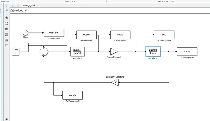
*The above image is the designed model.
*The model is finally saved and run.
*The plots have been made to observe the output.
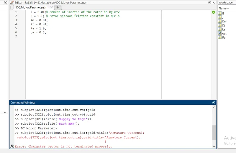
*The output graphs has been pasted for reference.
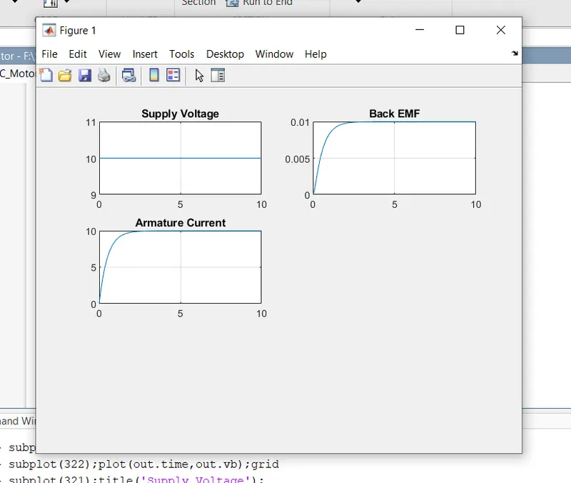
*Thus the stability of the system has been analysed from this graph.