Project 1
PROJECT 1:
Development of a forward energy-based fuel consumption model of a conventional vehicle.
Aim:
1) To compute the fuel economy numbers for the given vehicle (kmpl) on the urban cycle (UDDS) and highway cycle (HWFET).
2) To analyze and understand the vehicle operating points in terms of engine speed, torque, transmission speeds, pedal positions, gear, distance traveled, etc.
3) Tabulate the fuel economy numbers (kmpl) for UDDS and HWFET cycle.
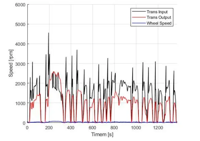
4) Plot the time trace for engine, transmission input, transmission output and wheel speed on one plot.
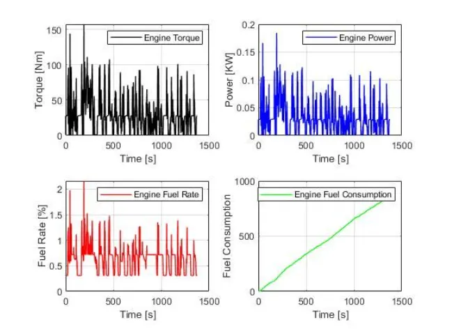
5) Plot engine torque, engine power, fuel rate and fuel consumption using subplots.
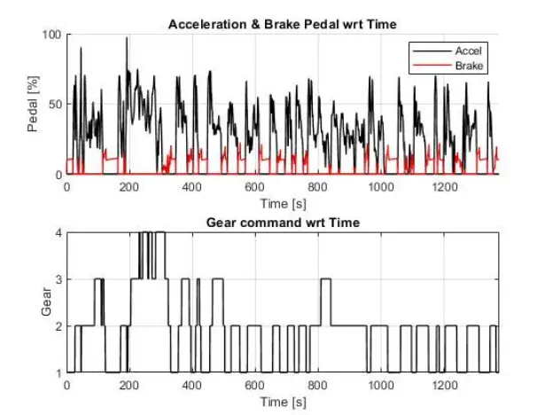
6) Plot accelerator and brake pedal, gear command, vehicle desired and actual speed, vehicle distance using subplots.
7) Plot the engine operating points on the engine fuel map.
8) Generate the plots for both drive cycles.
9) Write down appropriate brief comments on each of these plots, describing the vehicle behavior throughout the drive cycle.
10) Study of Conventional vehicle simulink model and creates graphs.
Conventional vehicle :
Conventional vehicle is a type of vehicle which uses fuel based internal combustion engines like petrol or diesel to run the engine inorder to propell the engine.It is the widely used type of vehicle which is currently being used.The disadvantages of using this conventional type vehicle is that the losses are high and also they release harmful gases which are dangerous to humans and atmosphere.
Forward modelling approach:
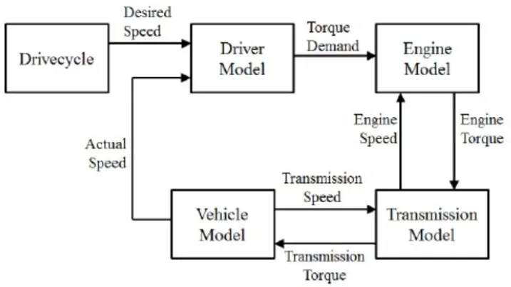
- The forward modelling approach is also known as cause-effect, engine-to-wheel or rear-to-front method. The direction of calculation is the same as the direction of positive power flow, from engine-to-wheel.
- This approach is based on vehicle dynamics equations and the behaviour of each powertrain components and their dynamic interaction.
- Moreover, a driver controller is required to control the vehicle to follow a desired speed and set the start of the calculations. The controller is implemented to model the driver that will either push the accelerator or the brake pedal to match the desired speed which enables to study the driver behaviour. The controller is used as part of a feedback loop that will determine the energy required to drive the vehicle.
Matlab scripts :
Here all the required variables are loaded and the driver selection is done.Before running the simulink model we have to run this script initially.
%%%%%%%%%%%%%%%%%%%%%%%%%%%%%%%%%%%%%%%%%%%%%%%%%%%%%%%%%%%%%%%%%%%%%
In this project, a typical midsize car with a 1.9L engine and a 4-speed automatic transmission is considered. Data is taken from ADVISOR data base developed by NREL, USA. Transmission shift map and controller is taken from Matlab/Simulink example database.
The model developed has the capability to simulate the vehicle on different drive cycles like UDDS, HWFET, FTP, NEDC, etc.
“Project1_InitFile.m” is a Matlab script used to load all the variables required for running the Simulink model and for post-processing. The drive cycle selection is also done here. Before running the Simulink vehicle model, run this initialization script.
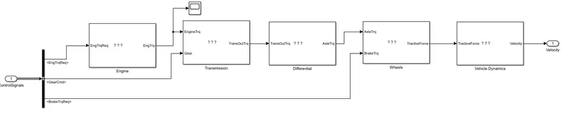
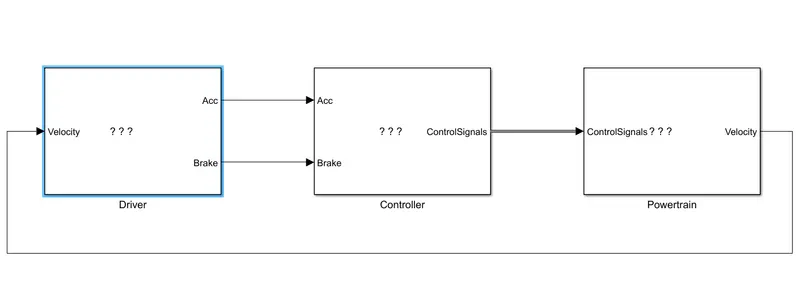
The simulink model of a conventional vehicle is given above and the individual details will be explained now.
Driver Model :
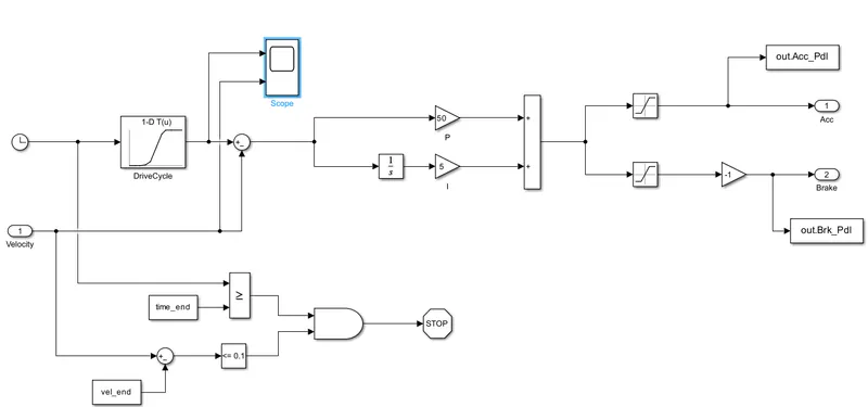
This is a basic pi controller which uses the driver inputs and generates the accelerator and brakes pedal output.It is based on time, velocity then its all integrate and creates output accelration pedal and brake pedal.
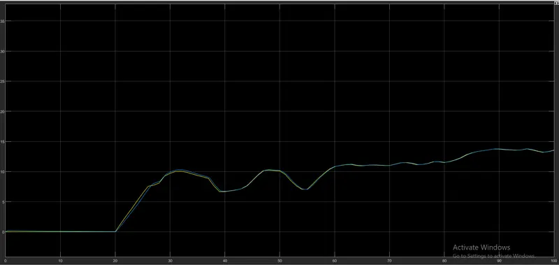
Output of the driver model through scope :
Controller model :
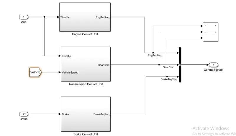
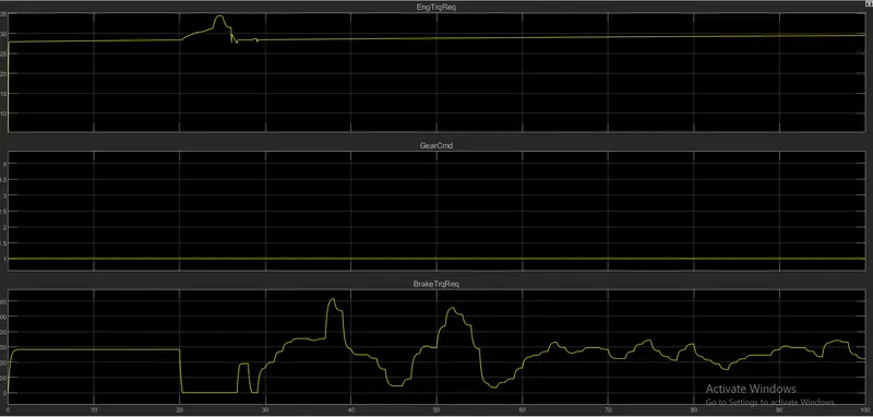
Based on the driver inputs the controller model generates torque,gear and brake torque.These inputs are fed to the ‘Powertrain’ block which represents the drivetrain of the vehicle.
Output created by controller block
Engine contol unit :
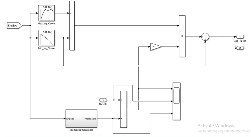
In this control model We use engine control unit in that give input Engine speed through creating look up table. in that table we give input Maximum torque and map speed then also create 2nd look up trable in that give input ct torque and map speed then it substracts and multiplied. the engine speed also give to ideal contro speed to integrate from this we meet output of engine required torque.
Transmission control unit :
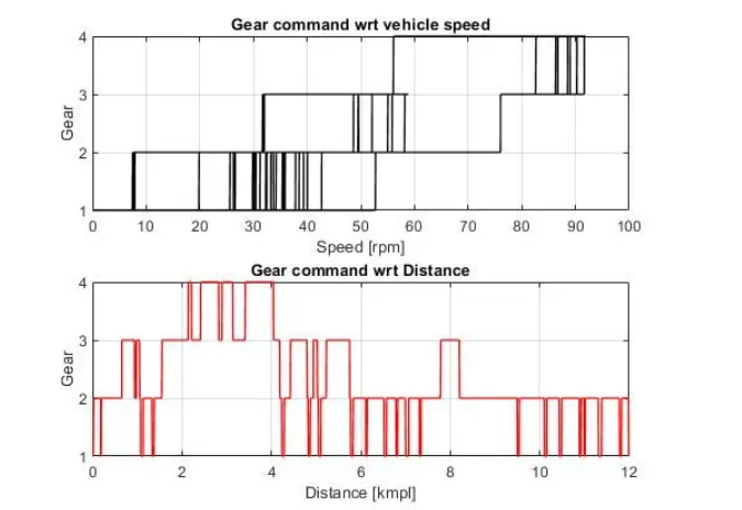
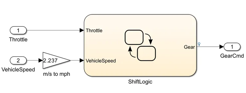
In this unit we create steadfy flow variable state for controlling of gears of vehicle as in ascending and descending order with respect to time, speed, distance. and give input to this steady state is vehicle speed in m/s to mph.
Brake torque :
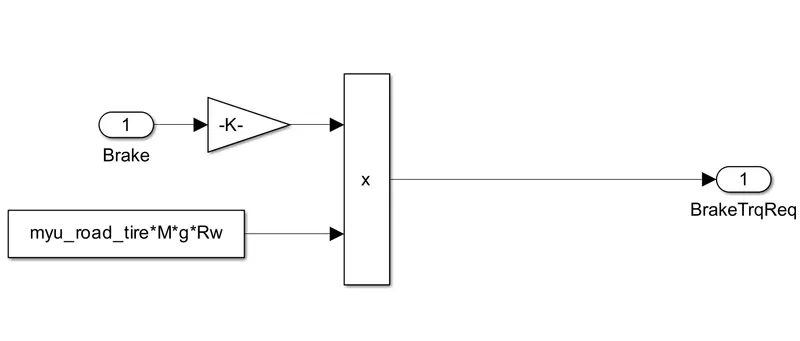
It is used to calculate the break torque.
Power train :
Power train converts all the energy into the desired motion of the vehicle.It consits of engine,transmission,wheels,differential and vehicle dynamics.
Engine :
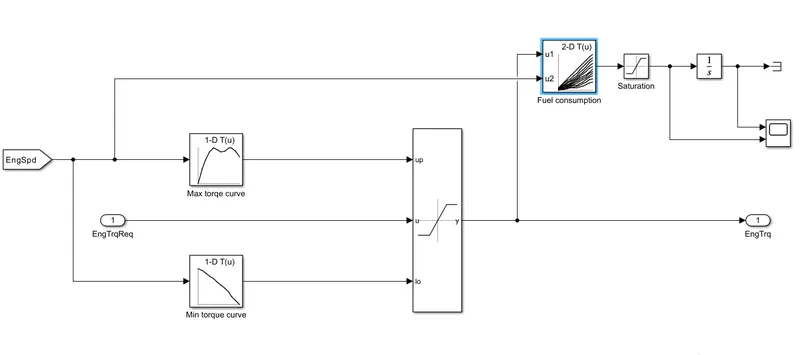
- Based on the Engine speed The required torque from the controller is saturated between Max torque curve and min torque curve and passes the Engine torque to the Transmission block
- The 2D lookup table is used to calculate the fuel flow rate based on engine speed and engine torque. The fuel flow rate is then integrated to find the fuel consumption.
- Estimated fuel flow rate, fuel consumption, engine torque and engine speed are passed to the MATLAB workspace using the to-workspace block.
- Engine fuel flow rate and Fuel consumption are scoped.
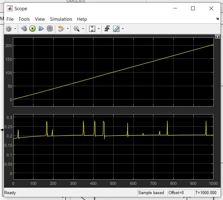
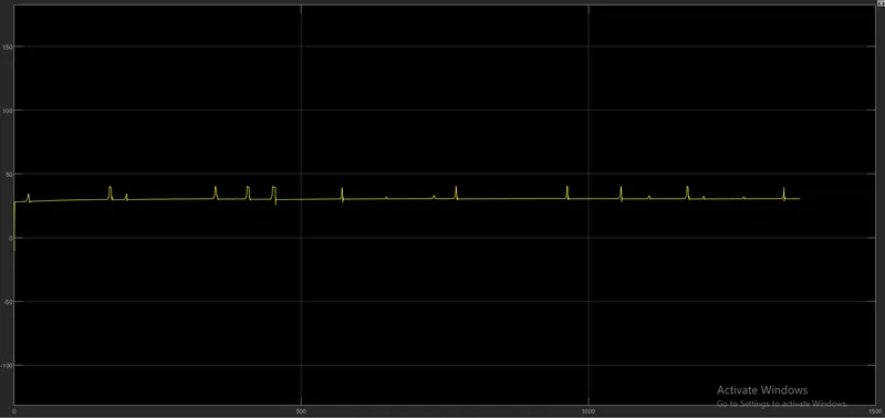
Scope view of the engine torque:
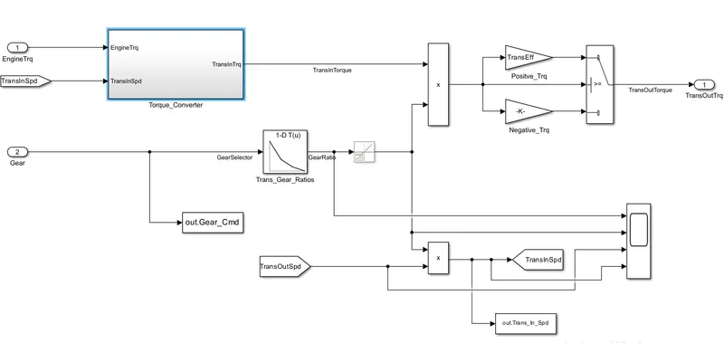
Transmission model :
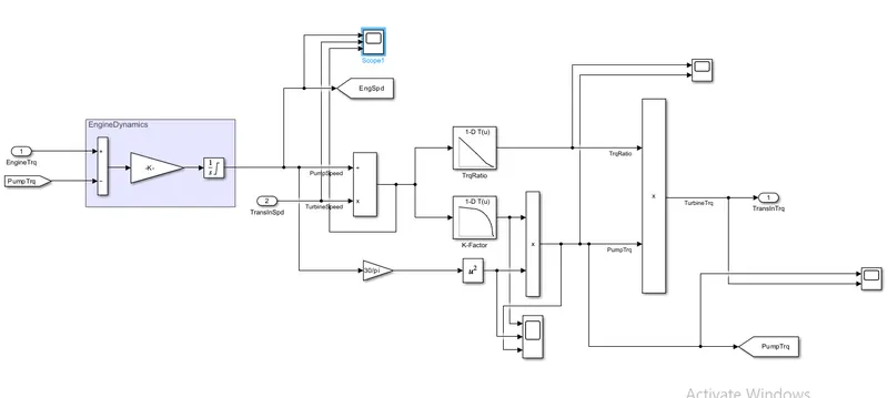
- The engine block is connected to the automatic transmission via a torque converter. The output of the transmission is connected to the differential.
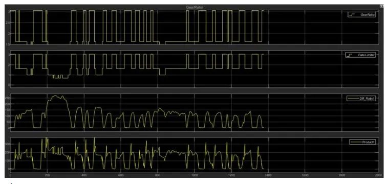
Scope view for transmission model :
Torque converter :
Differential block:
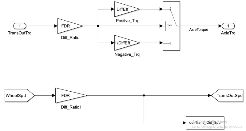
In this taking input is the transmission output then its going to the differential ratio multiplied the output and input torque then meet axle torque. The axle torque is a lower than the transmission torque and differential ratio.
Wheels :
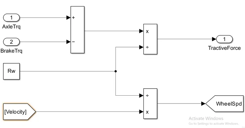
In this model we take the axle torque from differentail and brake torque from controller. it is substracts and multiplied rolling radius and velocity then we meet the tractive force from axle and brake torque. and the wheelspeed is meet using velocity.
Vehicle dynamics :
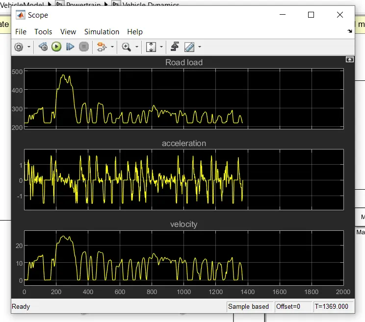
Equation for calculating road load.

Where,
p = air density [kg/m^3]
A = Frontal area [m^2]
Cd = drag Coefficiend
Vveh = velocity of vehicle [m/s^2]
Vwind = velocity of wind [m/s^2]
Cr = rolling resistance coefficient
M = mass in [Kg]
g = gravity.
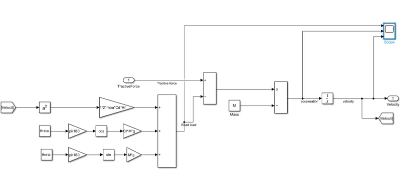
Graph for road load,acceleration and tractive force.
For creating Plots we use MATLAB coding So the coding will give down:-
1) Plotting vehicle characteristics time trace transmission IN/OUT and Wheel Speed:-
2) Plotting vehicle characteristics time trace to Engine speed, Engine Torque, Engine Power, And Engine fuel rate, Engine fuel consumption:
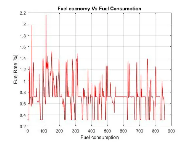
3)Plotting fuel economy Vs Engine Fuel consumption:-
4) Plotting Accelerator pedal, Brake pedal and gear command with respect to time:-
5] Plotting gear command vehicle desired with actual speed:-