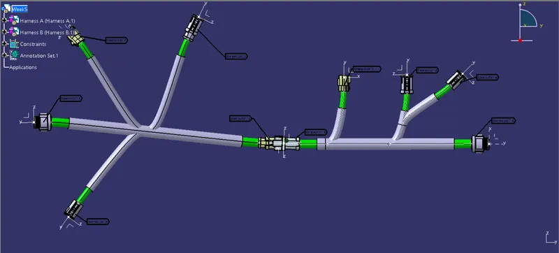
Wiring harness design in CATIA V5 - 3D modeling Week 5 & 6 Challenge
Aim - Route the following harness layout in Electrical workbench. Make assumption for harness bundle diameters. Use the connectors provided
Objectives-
- Check the bundle Continuity
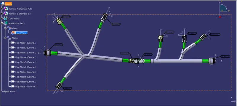
- Add annotation to all connectors.
- Check for the bundle warning.
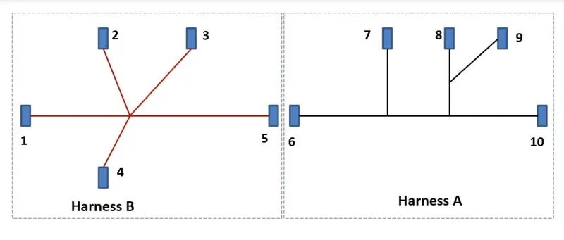
Figure shows the layout of two Harness A and Harness B
- The electrical connectors are represented by numbers in the above figure. There are 8
different types of connectors at 10 different locations. - Bundle continuity has to be checked for the two created harnesses.
- After the two Harnesses are created, the next objective is to have them interconnected electrically.
- Check for bundle warnings in Harness A and Harness B
- Add annotations to all the connectors in Harness A and Harness B
- Define connectors one by one
Define all the electrical connectors geometrically and electrically so that they can be used in the wiring harness
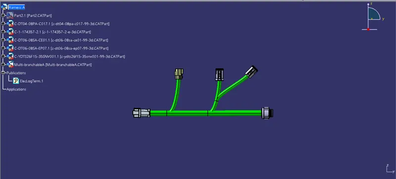
Harness A connectors
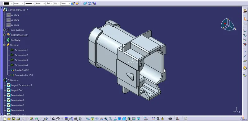
1. C-DT04-08PA-C017
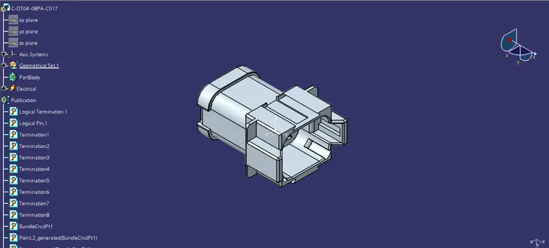
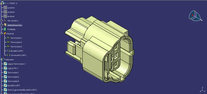
2. C-1-174357-2
3. C-DT04-08PA-C017
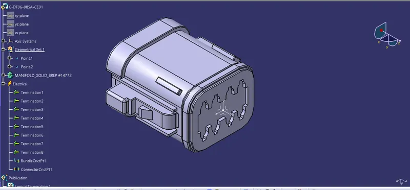
4. C-DT06-08SA-CE01
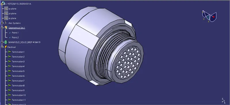
5. C-YDTS26F15-35SNV001A
Harness A Routing -
Harness B connectors -
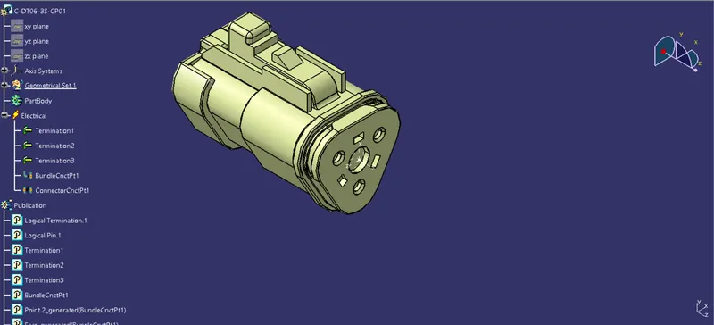
1. C-DT06-3S-CP01
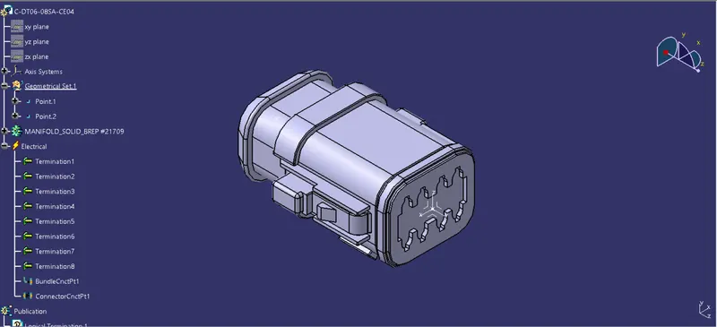
2. C-DT06-08SA-CE04
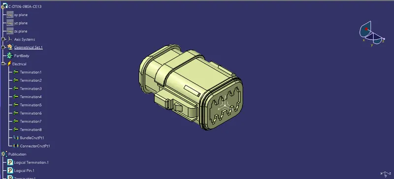
3. C-DT06-08SA-CE13
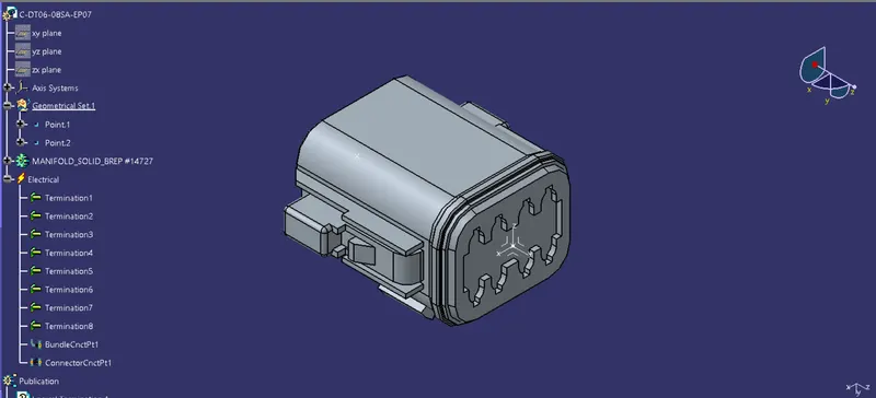
4.C-DT06-08SA-EP07
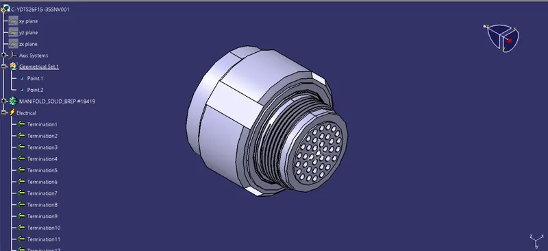
5. C-YDTS26F15-35SNV001
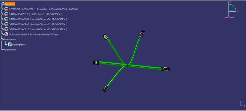
Harness B Routing
Now create a product of both routing
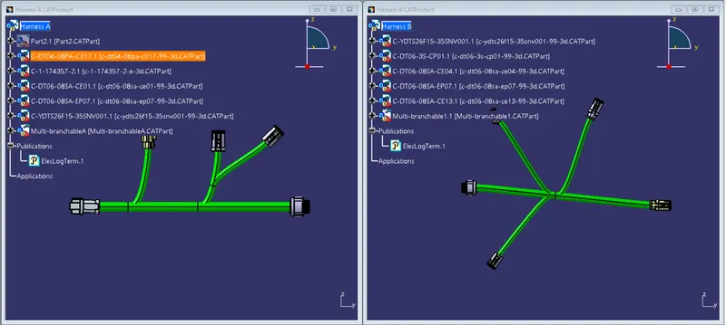
Connector is added with connect electrical devices
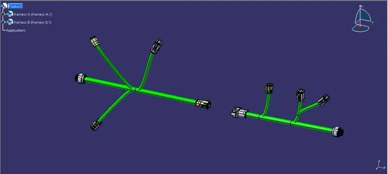
Now we need to connect both harness together so lets connect them using connect electrical devices
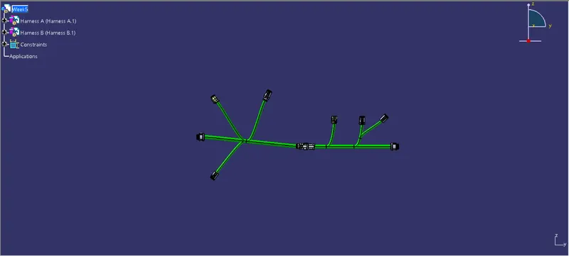
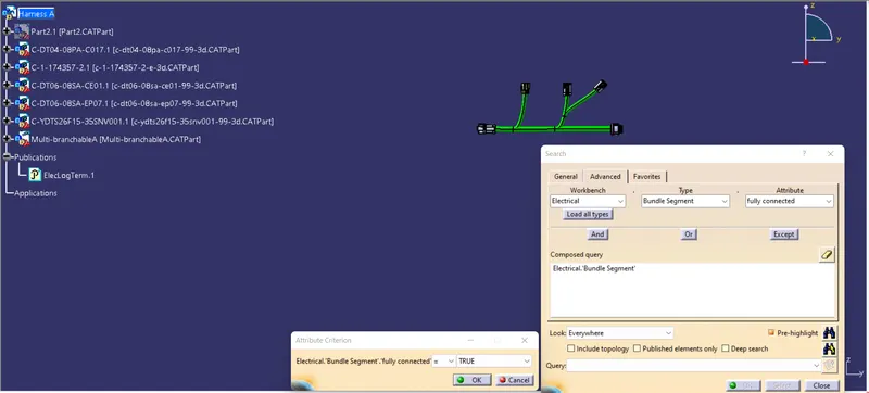
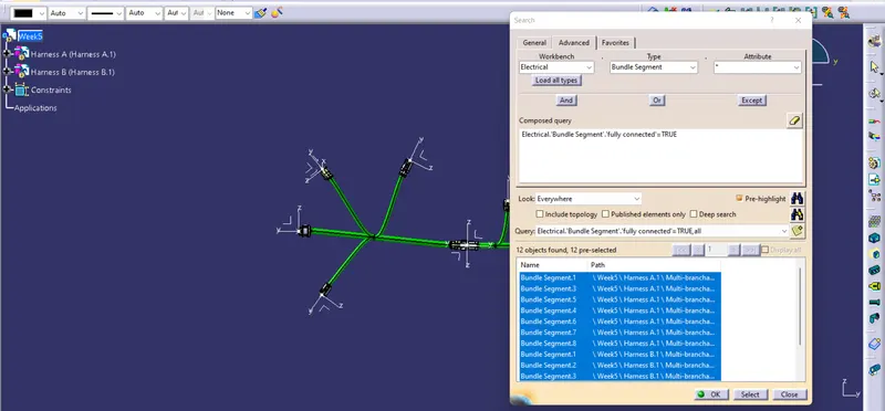
Now we need to check bundle connectivity whether the bundles are fully connected or not
for this we need to go to design representation mode and then need to select required parameters
Connectivity of harness A
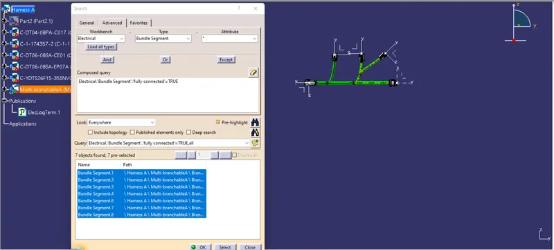
Connectivity of harness B
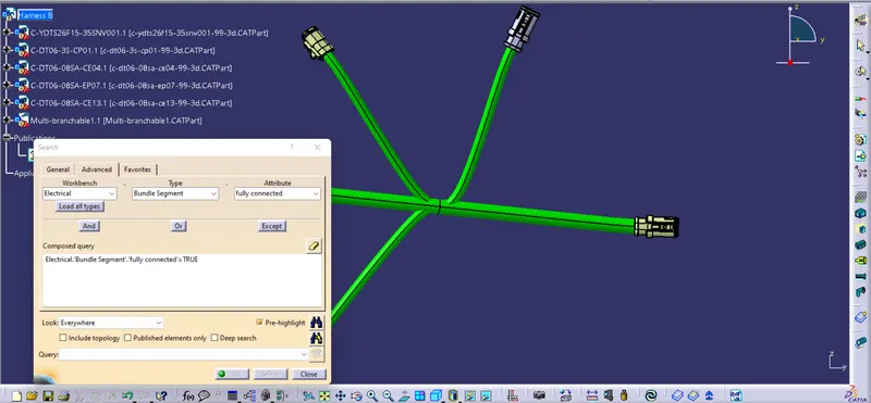
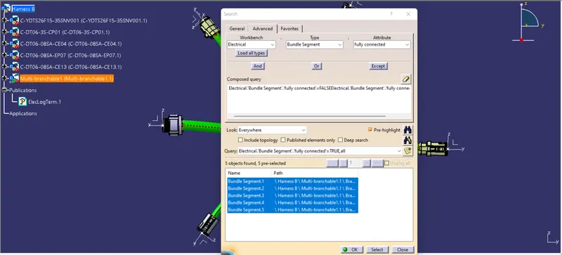
Assembly Connecticty
Annotations
- Switch to assembly design workbench
- Geometrical bundle needs to be active
- select front view or annotation plane
- select plane where we need annotation
- select flag note with lader icon
- select reference ponit
- Give annotation