Wiring harness design in CATIA V5 - 3D modeling Week 5 & 6 Challenge
Topic - Routing the harness A & harness B as given in image and electrically connecting them in Catia V5
Objective - To download the connectors from the open source
To define the parts electrical in electrical part design
To add the parts in respective catlogues
To route the connectors using bundles
To add protective covering to the bundles
To electrically connect the two harnesses
Introduction
Wiring harness is one the most essential parts of the vehicle industry. A wiring harness is an organized set of wires, terminals and connectors that run throughout the entire vehicle and transmit information and electric power, thereby playing a critical role in “connecting” a variety of components. Power and information travel through this network much like the circulatory and central nervous systems of the human body. It conducts electricity for all electrical loads on a vehicle
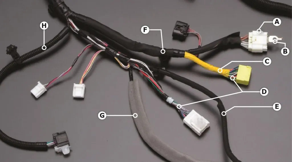
Selection of components
Selection of connectors, fuses, lights, switches, sensors, wires, cables, relays, protection tubes, motors etc. are the core components of the wiring harness. The performance of these components directly determines the overall performance of the wiring harness and plays a decisive role in the stability and safety of the whole vehicle. The basis of the selection of these components is the voltage system and its current carrying capacity. Ambient temperature in the selection of these components is one of the most important aspects of wiring harness design. Proper selection of these electrical components and their conductors ensures reliability and safety. For example, for the requirements of high performance airbags like ABS and ECU with a terminal connector, gold-plated pieces are preferred to ensure safety and reliability
Wiring Diagram
Wiring diagrams are also known as schematics or circuit diagrams. The selected components are placed and connected to each other in the diagram. These components belong to a set of libraries which can be modified and configured according to customer specific requirements. A wiring diagram shows each connection in detail. The schematics give an overview of the components that are part of the electrical design. Other items in the schematics are for example cables, sheet cross references and ECUs.
If an assembly is going to be used for communications or data signal transmission, twisted pairs should be considered to eliminate the risk of noise or EMI (electromagnetic interference) impacting on the performance of the assembly.
Connectors
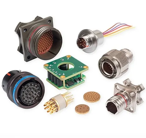
An electrical connector is an electromechanical device used to create an electrical connection between parts of an electrical circuit, or between different electrical circuits, thereby joining them into a larger circuit. Most electrical connectors have a gender – i.e. the male component, called a plug, connects to the female component, or socket.
Protective covering - Cot tubes
Corrugated Flexible Tubes also known as Cot Tubes / Convoluted Conduits have a wide range of application for harnessing cables in: • Automobiles: HCVs / LCVs / Four Wheelers / Two Wheelers. • Electrical Control Panels. • Home Appliances: Washing Machines / Fridges. • Railway Coaches
Route the following harness layout in Electrical workbench. Make assumption for harness bundle diameters. Use the connectors provided. After completion of routing,
- Check the bundle Continuity. Add snap of result in submission
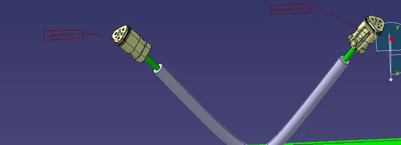
- Add annotation to all connectors. Make an assumptions for annotations like connect 1 , 2 etc
- Check for the bundle warning. Add snap.
- Generate CAT.part of harness assembly and convert is in. igs format.
Download the connectors from open source
Go to part design and using point and axis place then in connector connection point and bundle connection point
Go to electrical part design and define the connectors electrically with connector connection point and bundle connection point
Add the connectors to the respective catalogues
Open a new product file in electrical assembly design and add all the connectors
Place the connectors according to the image given above
Make the product file as electrical geometrical bundle
Route the bundles to all the connectors and also use branch point
Add protective covering to the bundles as given in question using the catalogue
Go to electrical assembly design and connect the two harnesses
Harness B
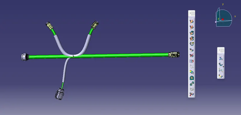
Harness B analysis of bundle continuity
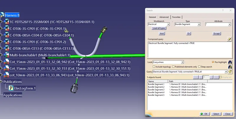
Check bundle warning of Harness B
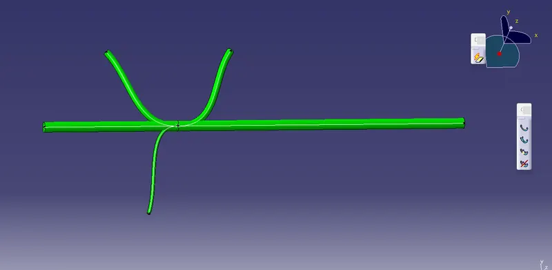
Harness A
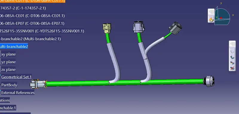
Harness A analysis of bundle continuity
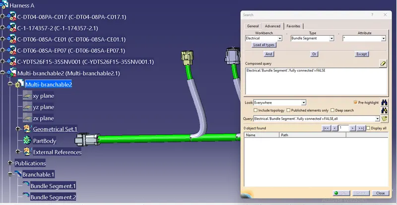
Check bundle warnings of harness A
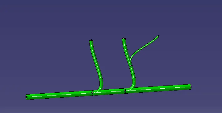
Assembly of Harness A with Harness B
3D Annotations given to the connectors
Conlcusion
We have succesfully routed harness A and Harness B and connected them electrically by doing analysis of bundle continuity in Catia V5