Photo Realistic Rendering
Title - Modelling & Assembly Of American Chopper
Objective - To model, assemble and render all the parts/assembly of american chopper.
Introduction - The american chopper is an american built bike. We are going to model all the parts of the american chopper, assemble them and render the images of the individual parts and assembly. We are going to use the tools and features available in Solidworks and model the parts with the best possible method and also give suitable appearance.
Design Methodology/approach -
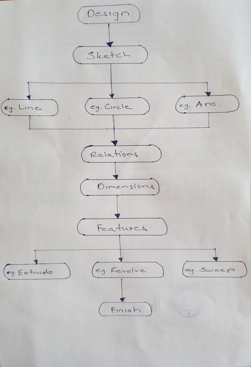
To design a model first, we have to select a suitable plane then sketch on it using sketching tools like Line, circle, Arc etc.
The next important thing to do is giving relations and appropriate dimensions to the sketch
Once the sketch is fully defined we have to use features like Extrude, Revolve, Sweep etc, and give a solid geometry to the part.
This concludes our modeling of a part.
Description - Tools/Features used in designing of the parts.
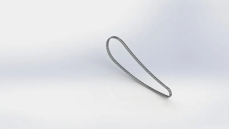
Chain
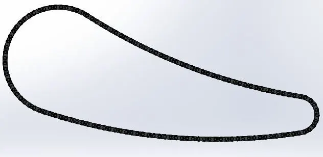
The sketching tools used in modeling a chain are circle, line, and 3 point arc.
The features used in modeling a chain are extrude, Fillet.
We also used blocks to make a pattern of the pins and links.
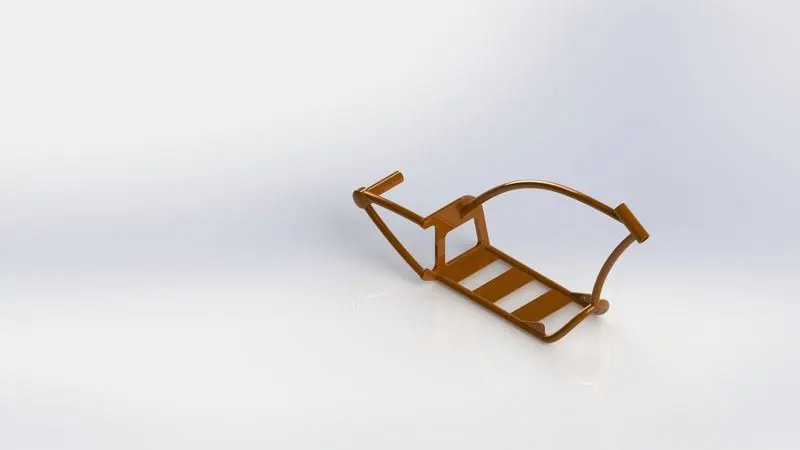
Chassis
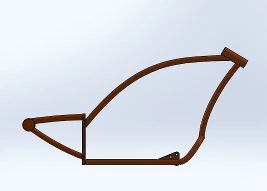
The sketching tools used in modeling the chassis are line, circle, and spline.
The Features used are projected curve, revolve, combine, sweep and split.
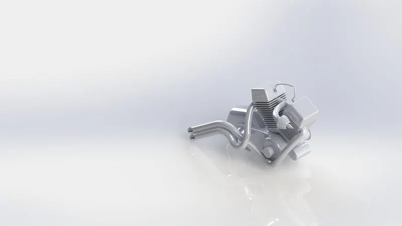
Engine
The sketching tools used in modeling the chassis are line, circle, rectangle and spline.
The Features used are projected curve, Extrude cut, Mirror, revolve, Dome, sweep and Linear pattern/circular pattern.
Oil Tank
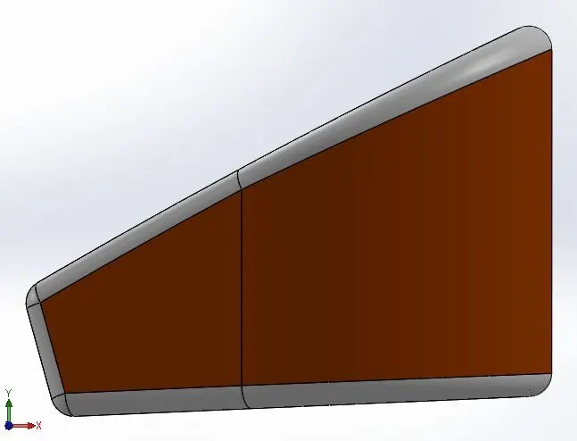
The sketching tools used in modeling the chassis are line and 3 point arc.
The Features used are Extrude and shell.
Tools
Line - Used to draw a line on a sketch
Circle - Used to draw a circle on a sketch
Arc - Used to draw an arc also con be used by hovering on a point after drawing a line.
Rectangle - Used to draw a square or a rectangle on a sketch.
Spline - Used to draw wavy lines with many points and can be designed using spline handle and weight.
Features
Extrude Boss/base - Used to give a solid geometry to a sketch.
Revolve Boss/base - Used to give a solid geometry in a circular pattern to a sketch.
Shell - Used to remove material from inside of a solid geometry
Linear Pattern/Circular pattern - Used to give a number of same geometry in a linear direction or a circular direction.
Sweep - Used to give a solid geometry in a given path.
Split - Used to remove unwanted material.
Projected Curve - Used to sketch a curve which cannot be drawn in between planes directly.
Dome - Used to dive a dome structure on the faces of solid bodies.
Extrude Cut - Used to remove material according to the sketch.
Fillet - Used to give a rounded edge to a part
Chamfer - Used to give a diagonal edge to a part.
Combine - used to make a single solid geometry linking 2 or more parts.
Mirror - Used to mirror a part.
Note: We have just given the parts in description which cover all the tools and features
Assembly Model -
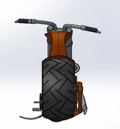
Front View
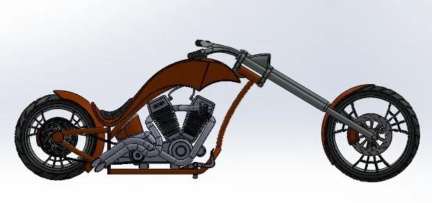
Side View
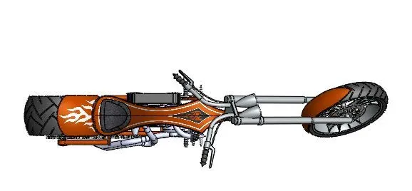
Top View
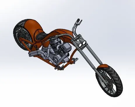
Isometric View
Camera Setup View
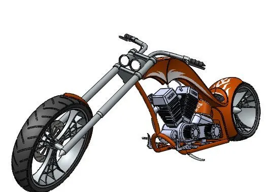
Rendering Images
Chopper Assembly
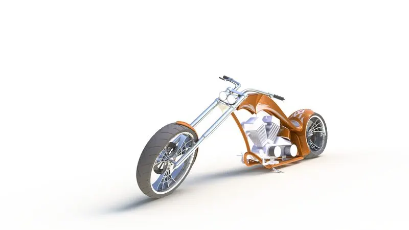
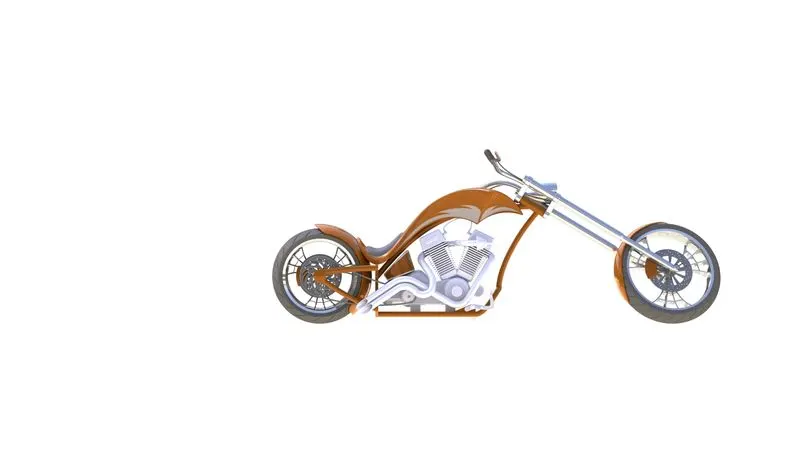
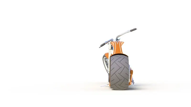
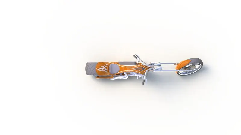
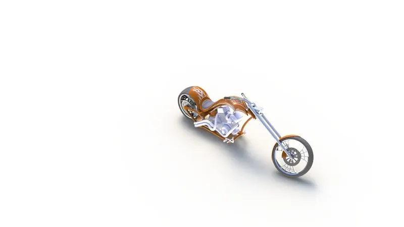
Part Images
Chain
Chassis
Engine
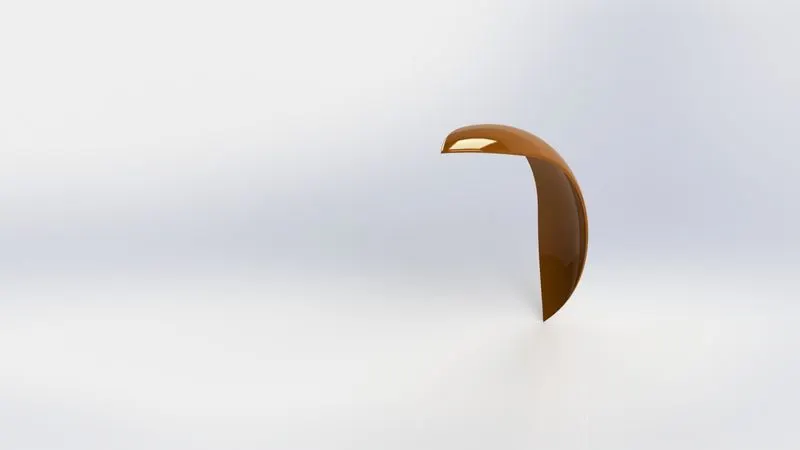
Front Fender
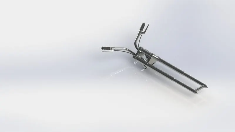
Front Fork
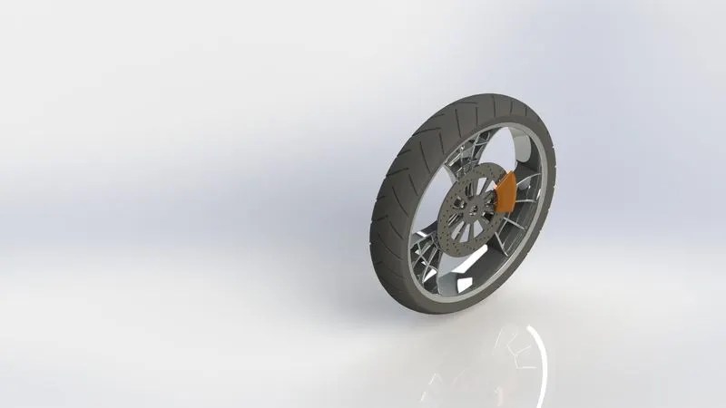
Front Wheel
Gas Tank
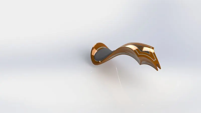
kick stand
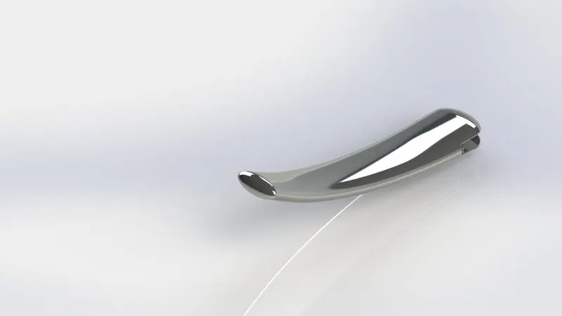
Rear Wheel
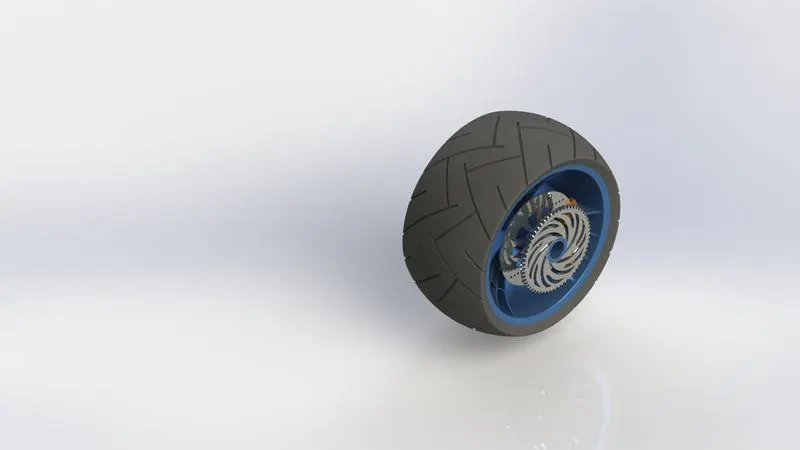
Transmission Belt
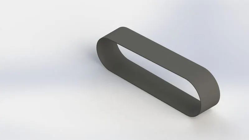
Rear Fender
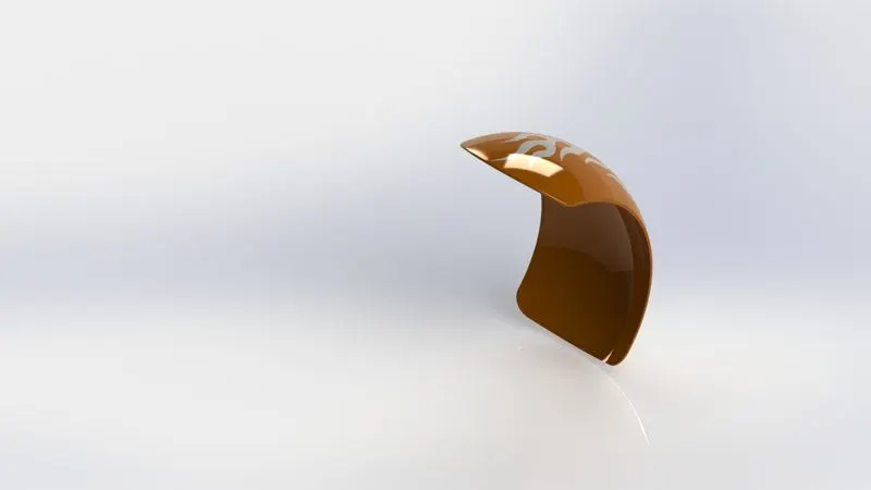
Pedal
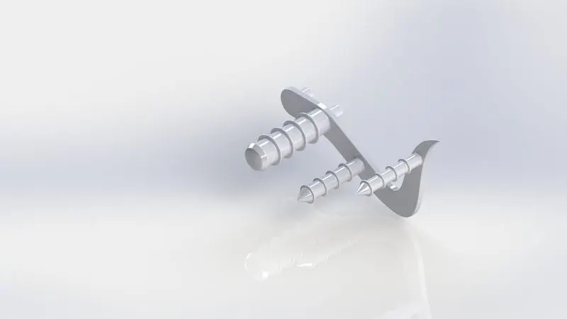
Oil Tank
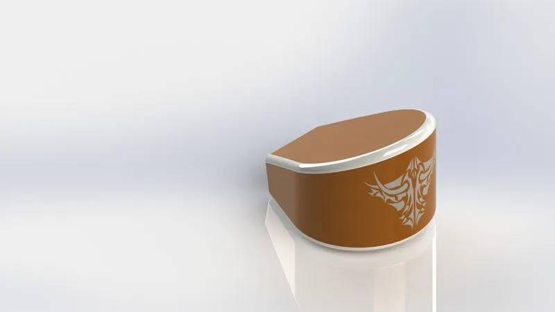
Conclusion - In the modeling and assembly of a American Chopper all the tools and features used cover all appraoch to design any part in Solidworks.