Week 8 - Challenge 1 - Base Bracket Design
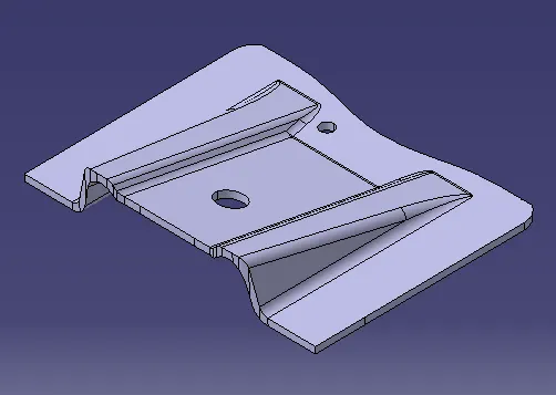
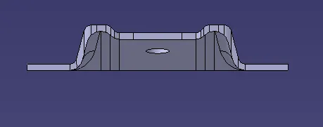
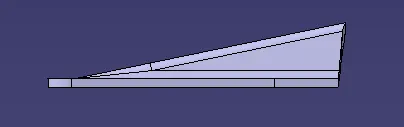
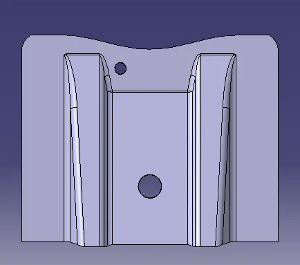
Base Bracket
Introduction - In this report we will be creating the Base Bracket using Class A as the input and then doing draft analysis on the component.
Approach - We will have Class A as the input of base bracket we had to create Class B and Class C surface using Class A.
Class A Surface - Class A surface is the input surface to create a thickened component in catia v5.
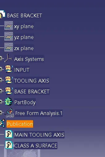
Tooling Axis - Tooling axis is the direction in which the core and cavity of the mould will move. Tooling axis is created by creating bisecting line in the direction in which all the features of the component will be covered. In the surface in which we have doubt first lines are created parallel to the surface and then the bisecting line is created.
Class B surface - Class B surface is created by ofsetting the Class A surface. First the class A Surface is extracted using the extract command then we untrim and extrapolate the surface.
Class C surface - Once the Class B surface is created, Class C surface was created by using the sweep command of class A surface.
Once all the three surfaces are created using the join command class C and class A surfaces are joined then trimmed with the class B surface
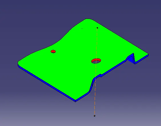
Draft Analysis - Once the component is created of a solid body. Draft analysis can be done using the feature draft analysis. In the draft analysis we can determine that the surfaces are within 3 degree angle which will help in manufacturing the component.
 \
\