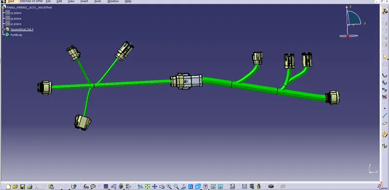
Wiring harness design in CATIA V5 - 3D modeling Week 5 & 6 Challenge
FIrst of all downloaded all the necessar connectors for the Harness B & Harness A seperatly from the link given in the question. After that fix the points and axis system to the connectors at the exact position of the connectors. The axis system is placed at the connector connection end of the connector.Same way located the points and axis system to all of the connecters. Then switch the Part Design work bench to Electrical part design work bench and define the connecter Ellectricaly by click on tool Connector and ther by give the no of terminals after that define connector connection point and bundle connection point same way define all the conneters Ellectricaly.
Opened a new product file for Harness A design, and pasted all the wanted connectors to the product file. Allignrd the connectors as per the drawing given the question. For that i created a drawing using lines in part design work bench and placed all the connectors a accordingly after that deleted the referance drawing. For alignment the connectors i used Smart move tool,Compas, Manipulation tool
For the creation of brancheble betwen the connectors switch the product file from Assembly Design work bench to Ellectrical Harness assembly work bench. Initialy defin the product file ellectricaly by click on Geometrical bundle tool and there by slect the top of the product tree structur. Using Multi branchable document tool created branch connection betwen the connectors according the drwing. InHarness A ther have 2 branch point in the main bundle and one branch point in the sub bundle branch so for creating the bundle connection point on the bundle use Add branch point tool.
After the bundle creation checked have any Warnings and cleared by adjusting the bundle length,bundle slack, also adjusting the position of the branch point. After that checed the Bundle Continuity of the Harness same way created the Harness B also.
Harness A Bundle Continuity checking
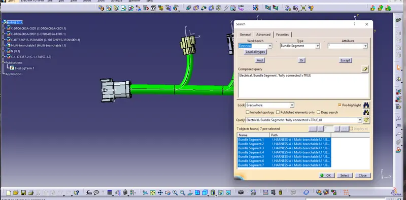
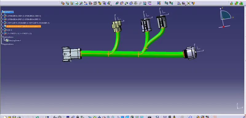
Harness A Bundle Continuity found Ok
Harness B Bundle Continuity checking
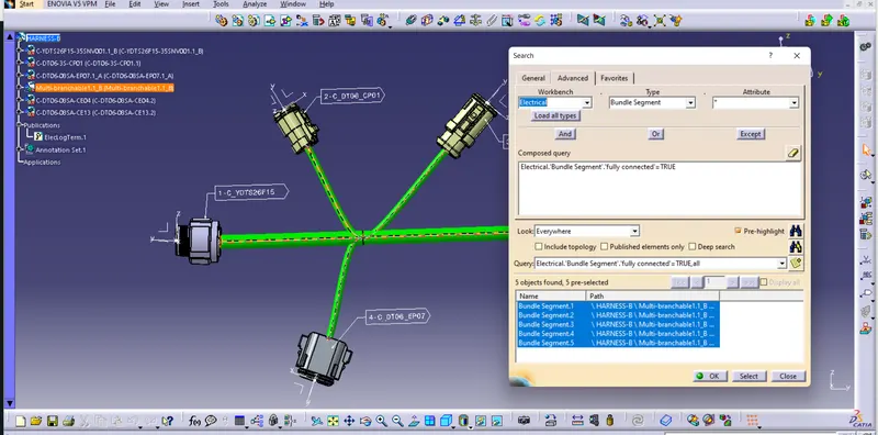
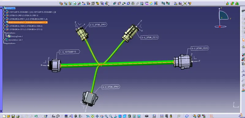
Harness B Bundle Continuity found Ok
Give annotation for all the connectors.
Harness A Harness B
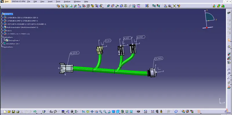
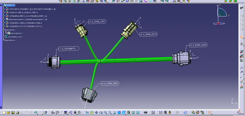
INTER CONNECTION OF BOTH 2 HARNESS A & B
For making the final assembly by connecting both Harness assembly Aand B opened a new product file and pasted both harness and placed the both harness assembly according with the drawing. By interconecting both the harnes we need to check the connecter in the harness's used for connect. both should have smae number of terminals and also one should be FEMALE Connector and another should be MALE Connector. Then switch to Ellectrical Assembly Design work bench ,then first click on top most portion of the product tree and after that click on Connect Electrical devices Tool shwon in the tool bar and click on the connector were going to connect.
Generating CAT Part and Convert in to IGS format
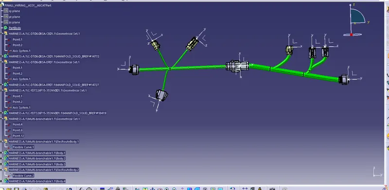
First need to switch the work bench to Assembly Design. Then in click on Tool option top of the window and click on Generate CAT part from PRODUCT. We can save CAT Part format and also save IGS format by Files - Save as - and change the format by selecting IGS format in the Save as type column.
STEP TO GENERATE CAT PART
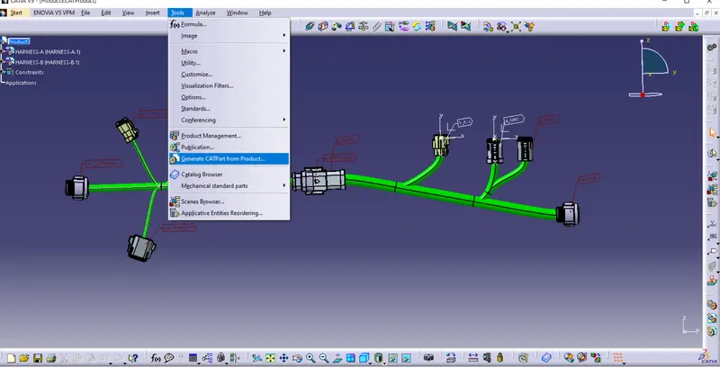
CAT part with Grafical colour added for bundle identification
IGS FORMAT