Wiring harness design in CATIA V5 - 3D modeling Week 5 & 6 Challenge
COMPONENTS USED:
1. C-DT04-08PA-C017 - Connector 1:
i. Download 3D Part: The 3D model is downloaded from the given link and saved as a Catpart file.
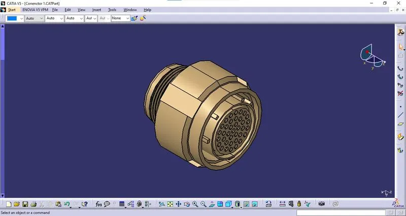
ii. Geometrical Parameters:
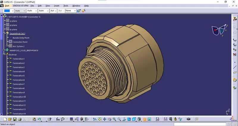
* Bundle Entry Point: The bundle entry Point is created at the rear part of the connector.
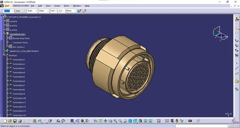
* Connector Point: The connector Point is created at the mating side of the connector.
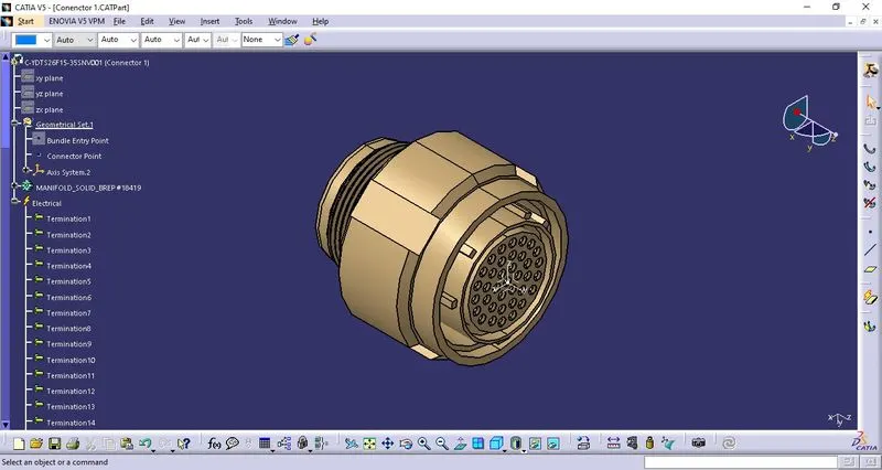
* Connector Axis: The connector axis is created with respect to Connector Point.
iii. Definition of Component:
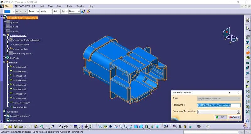
The component is defined as the connector using "Define Connector" tab in the "Electrical Part Workbench". The number of terminals is defined.
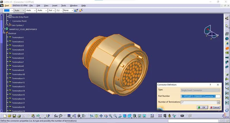
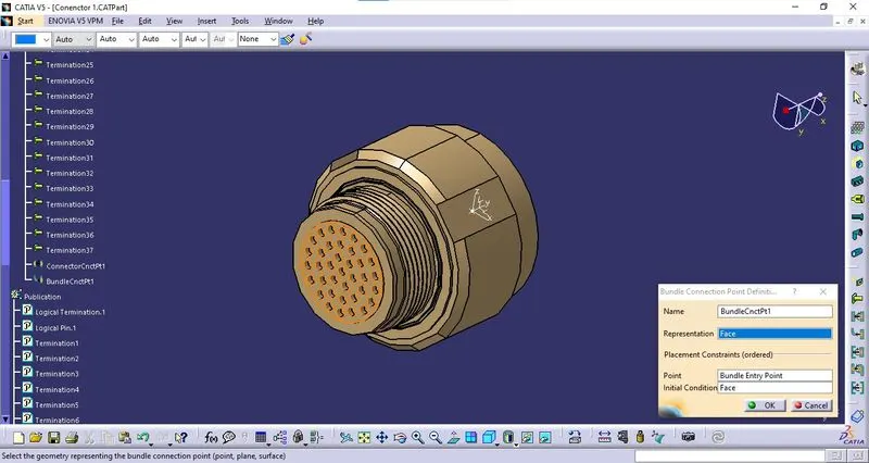
iv. Bundle Connection Point Definition:
The bundle connection point is defined using "Bundle Connection Point Definition" tab in the "Electrical Part Workbench". The parameters are defined appropriately.
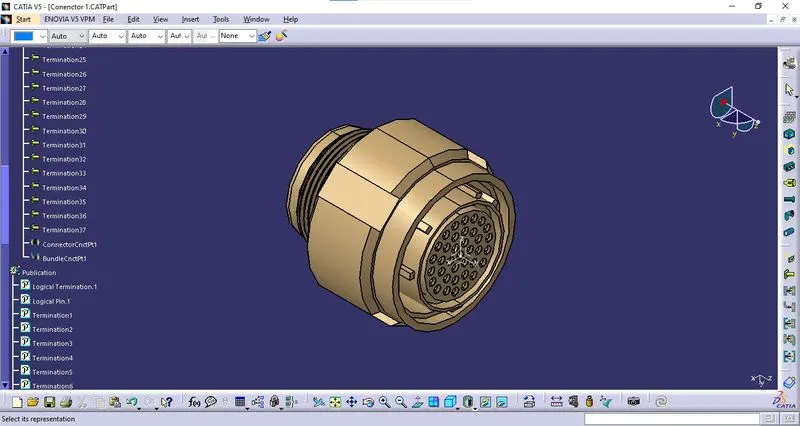
v. Connector Connection Point:
The connector connection point is defined using "Connector Connection Point Definition" tab in the "Electrical Part Workbench". The parameters are defined appropriately.
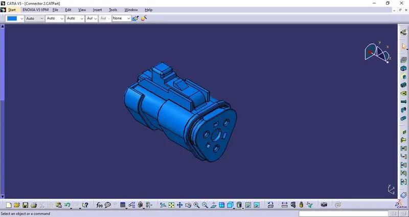
2. C-DT06-3S-CP01 - Connector 2:
i. Download 3D Part: The 3D model is downloaded from the given link and saved as a Catpart file.
ii. Geometrical Parameters:
* Bundle Entry Point: The bundle entry Point is created at the rear part of the connector.
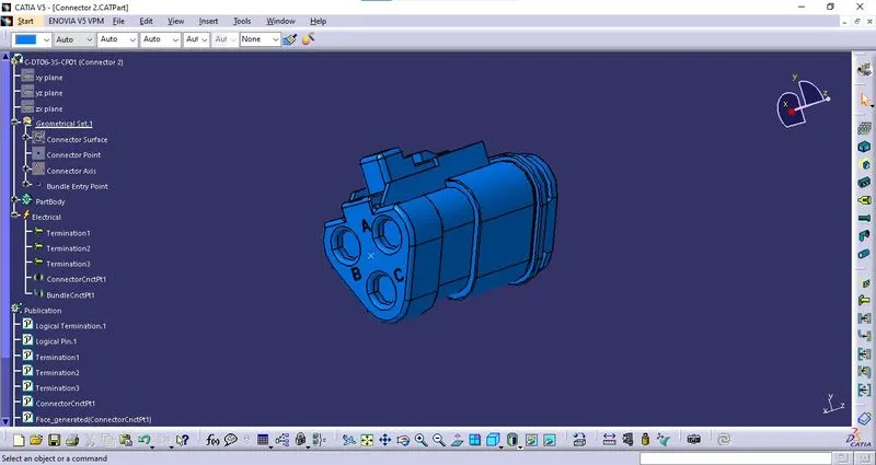
* Connector Point: The connector Point is created at the mating side of the connector.
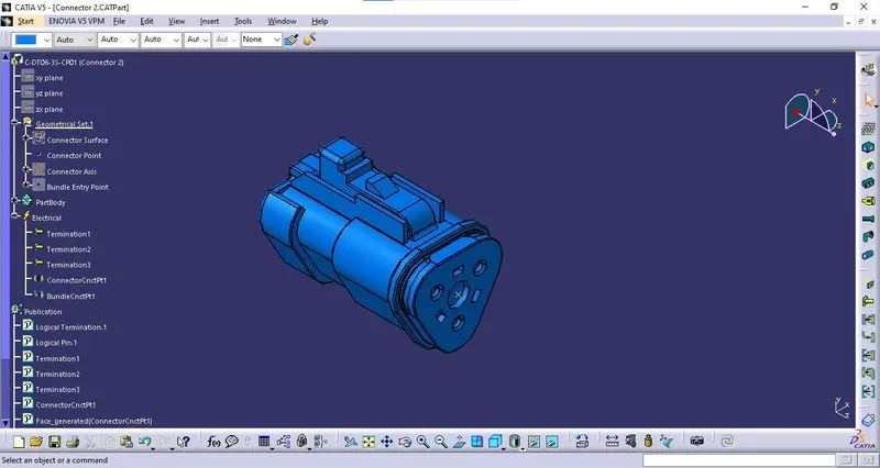
* Connector Axis: The connector axis is created with respect to Connector Point.
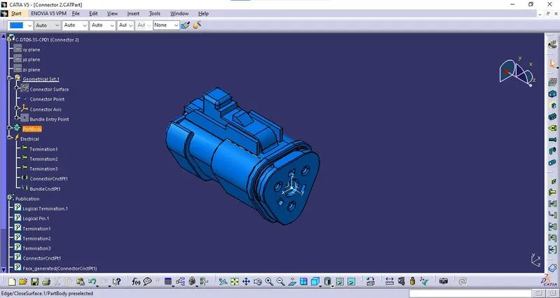
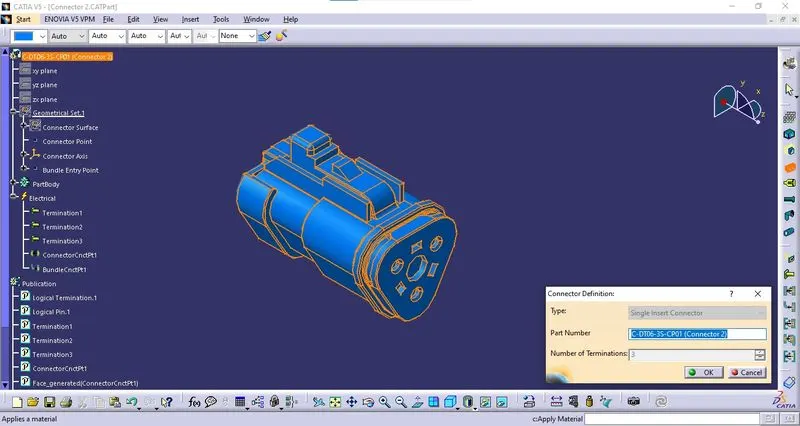
iii. Definition of Component:
The component is defined as the connector using "Define Connector" tab in the "Electrical Part Workbench". The number of terminals is defined.
iv. Bundle Connection Point Definition:
The bundle connection point is defined using "Bundle Connection Point Definition" tab in the "Electrical Part Workbench". The parameters are defined appropriately.
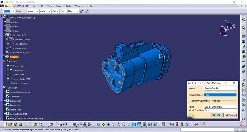
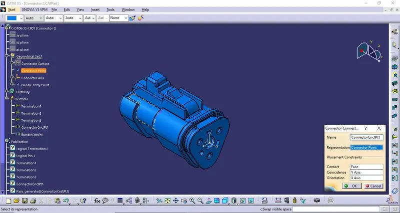
v. Connector Connection Point:
The connector connection point is defined using "Connector Connection Point Definition" tab in the "Electrical Part Workbench". The parameters are defined appropriately.
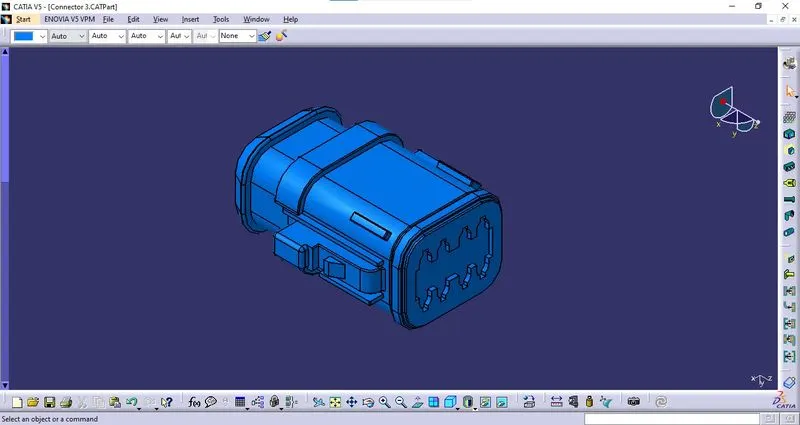
3. C-DT06-08SA-CE04 - Connector 3:
i. Download 3D Part: The 3D model is downloaded from the given link and saved as a Catpart file.
ii. Geometrical Parameters:
* Bundle Entry Point: The bundle entry Point is created at the rear part of the connector.
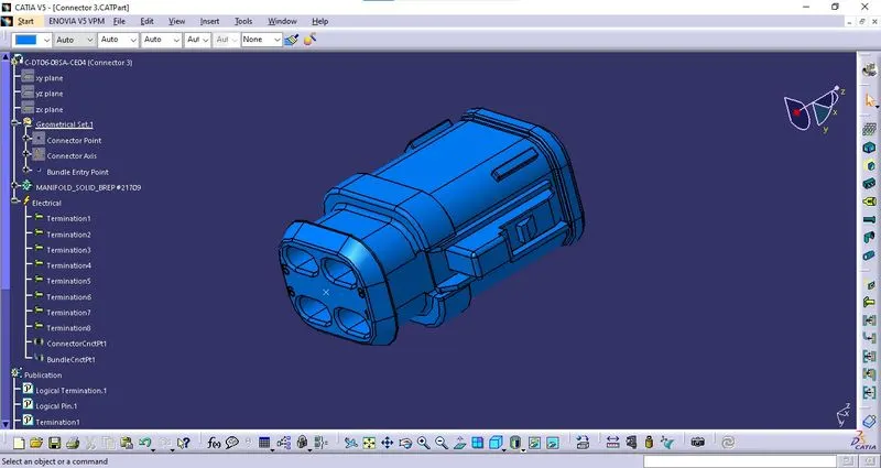
* Connector Point: The connector Point is created at the mating side of the connector. 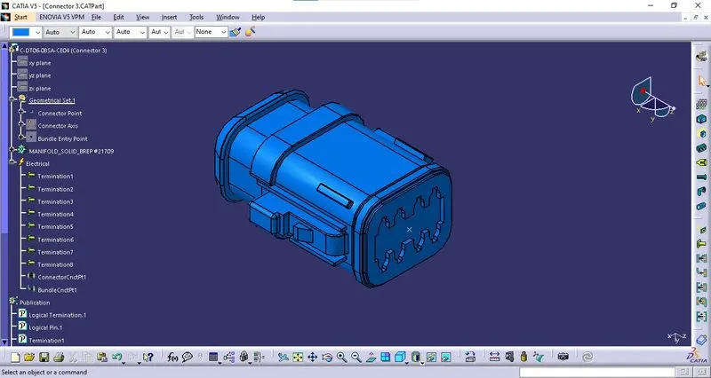
* Connector Axis: The connector axis is created with respect to Connector Point. 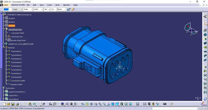
iii. Definition of Component:
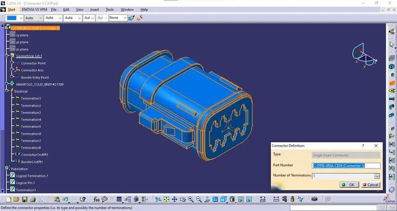
The component is defined as the connector using "Define Connector" tab in the "Electrical Part Workbench". The number of terminals is defined.
iv. Bundle Connection Point Definition:
The bundle connection point is defined using "Bundle Connection Point Definition" tab in the "Electrical Part Workbench". The parameters are defined appropriately. 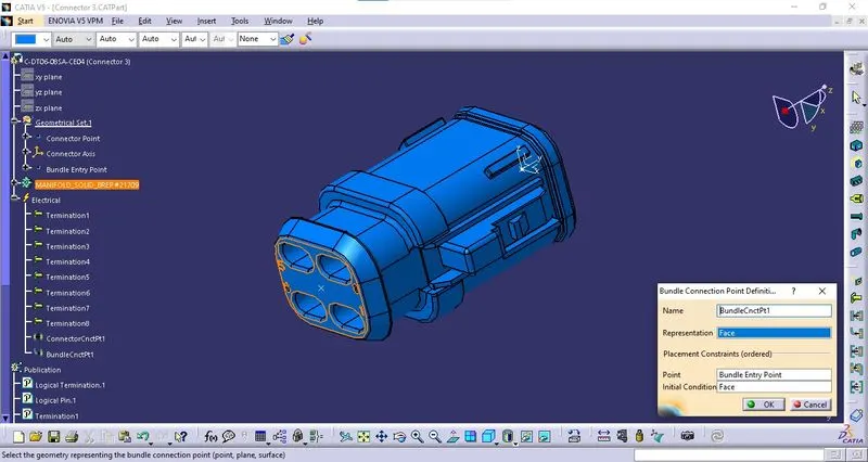
v. Connector Connection Point:
The connector connection point is defined using "Connector Connection Point Definition" tab in the "Electrical Part Workbench". The parameters are defined appropriately. 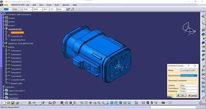
4. C-DT06-08SA-EP07 - Connector 4:
i. Download 3D Part: The 3D model is downloaded from the given link and saved as a Catpart file. 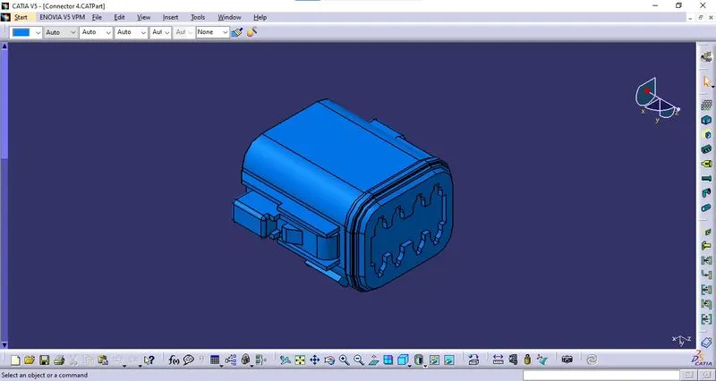
ii. Geometrical Parameters:
* Bundle Entry Point: The bundle entry Point is created at the rear part of the connector. 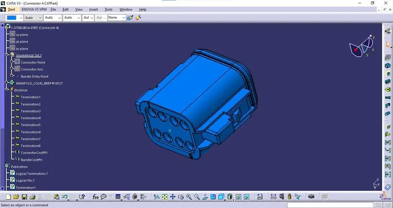
* Connector Point: The connector Point is created at the mating side of the connector. 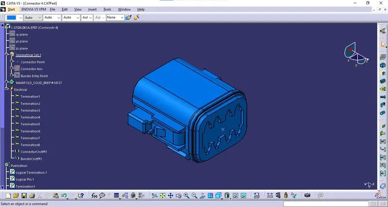
* Connector Axis: The connector axis is created with respect to Connector Point. 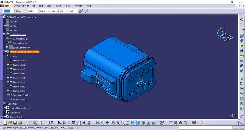
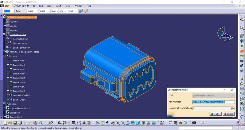
iii. Definition of Component:
The component is defined as the connector using "Define Connector" tab in the "Electrical Part Workbench". The number of terminals is defined.
iv. Bundle Connection Point Definition:
The bundle connection point is defined using "Bundle Connection Point Definition" tab in the "Electrical Part Workbench". The parameters are defined appropriately. 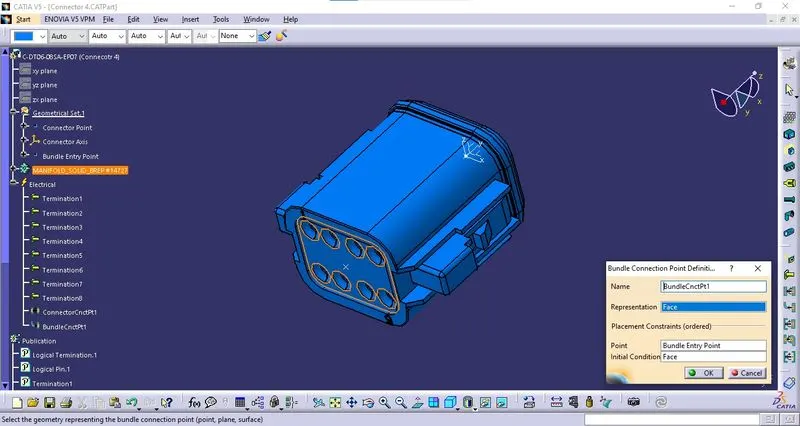
v. Connector Connection Point:
The connector connection point is defined using "Connector Connection Point Definition" tab in the "Electrical Part Workbench". The parameters are defined appropriately. 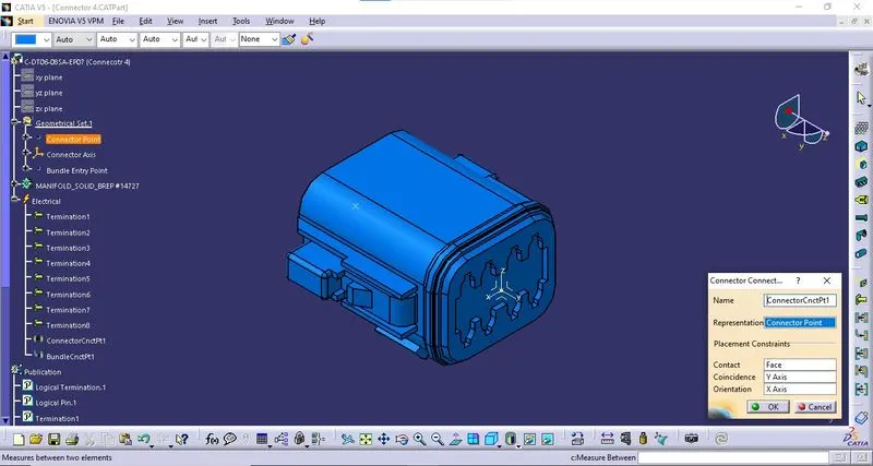
5. C-DT06-08SA-CE13 - Connector 5:
i. Download 3D Part: The 3D model is downloaded from the given link and saved as a Catpart file. 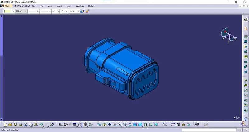
ii. Geometrical Parameters:
* Bundle Entry Point: The bundle entry Point is created at the rear part of the connector. 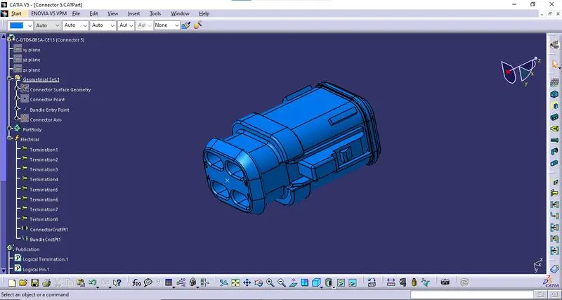
* Connector Point: The connector Point is created at the mating side of the connector. 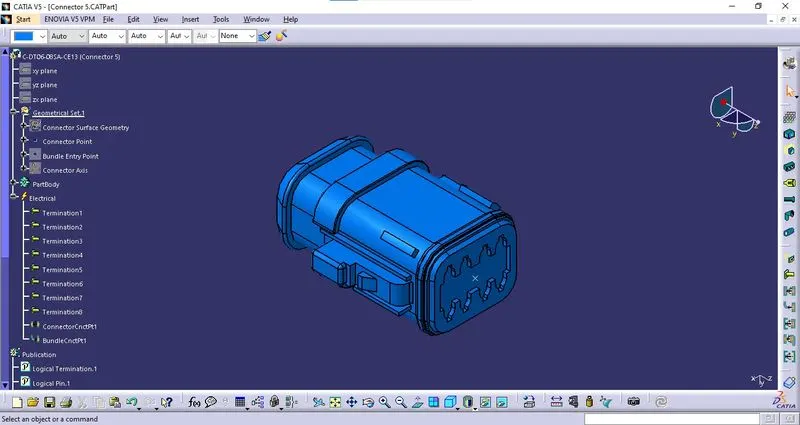
* Connector Axis: The connector axis is created with respect to Connector Point. 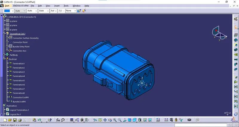
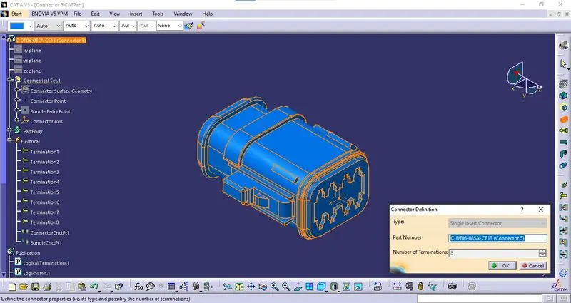
iii. Definition of Component:
The component is defined as the connector using "Define Connector" tab in the "Electrical Part Workbench". The number of terminals is defined.
iv. Bundle Connection Point Definition:
The bundle connection point is defined using "Bundle Connection Point Definition" tab in the "Electrical Part Workbench". The parameters are defined appropriately. 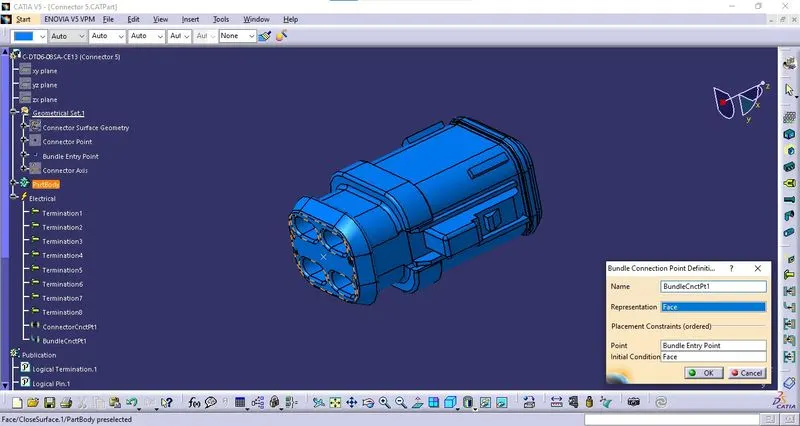
v. Connector Connection Point:
The connector connection point is defined using "Connector Connection Point Definition" tab in the "Electrical Part Workbench". The parameters are defined appropriately. 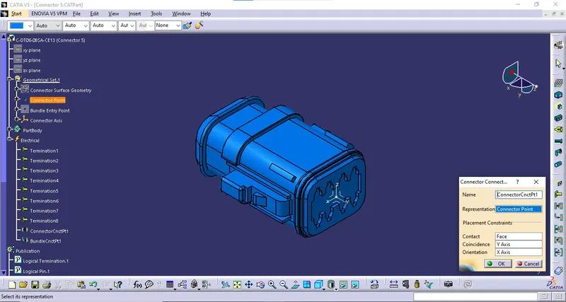
6. C-DT04-08PA-C017 - Connector 6:
i. Download 3D Part: The 3D model is downloaded from the given link and saved as a Catpart file. 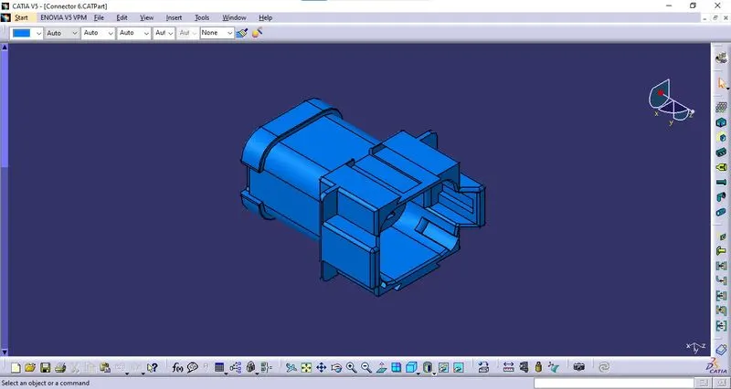
ii. Geometrical Parameters:
* Bundle Entry Point: The bundle entry Point is created at the rear part of the connector. 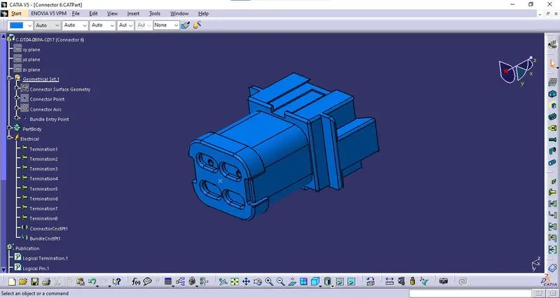
* Connector Point: The connector Point is created at the mating side of the connector. 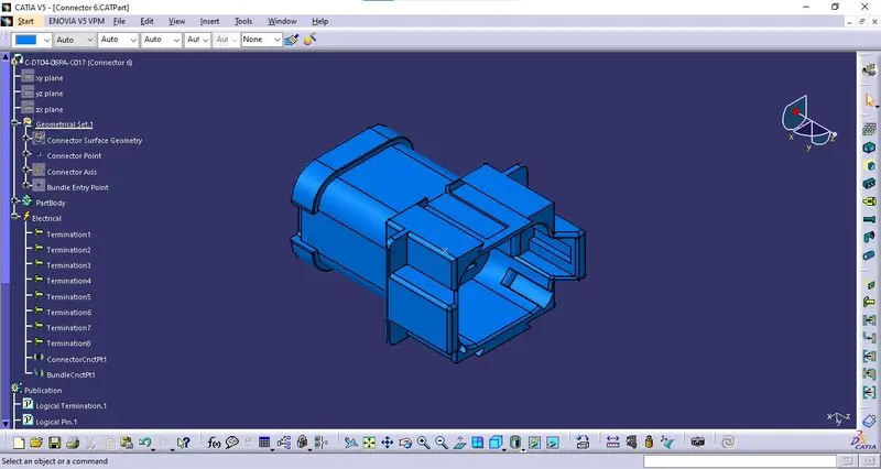
* Connector Axis: The connector axis is created with respect to Connector Point. 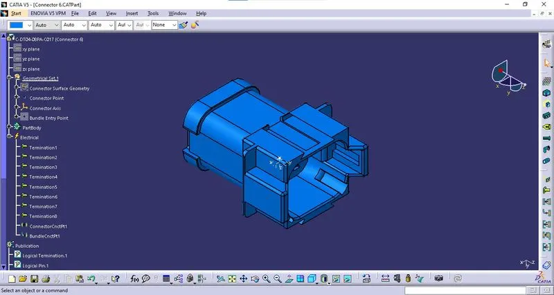
iii. Definition of Component:
The component is defined as the connector using "Define Connector" tab in the "Electrical Part Workbench". The number of terminals is defined.
iv. Bundle Connection Point Definition:
The bundle connection point is defined using "Bundle Connection Point Definition" tab in the "Electrical Part Workbench". The parameters are defined appropriately. 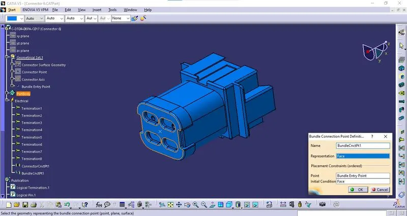
v. Connector Connection Point:
The connector connection point is defined using "Connector Connection Point Definition" tab in the "Electrical Part Workbench". The parameters are defined appropriately. 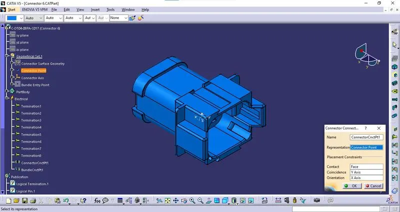
7. C-1-174357-2 - Connector 7:
i. Download 3D Part: The 3D model is downloaded from the given link and saved as a Catpart file. 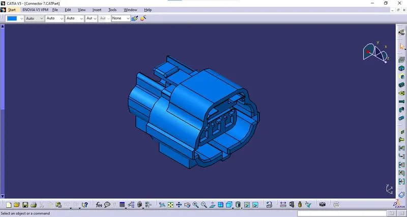
ii. Geometrical Parameters:
* Bundle Entry Point: The bundle entry Point is created at the rear part of the connector. 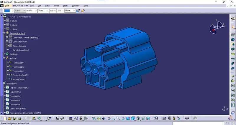
* Connector Point: The connector Point is created at the mating side of the connector. 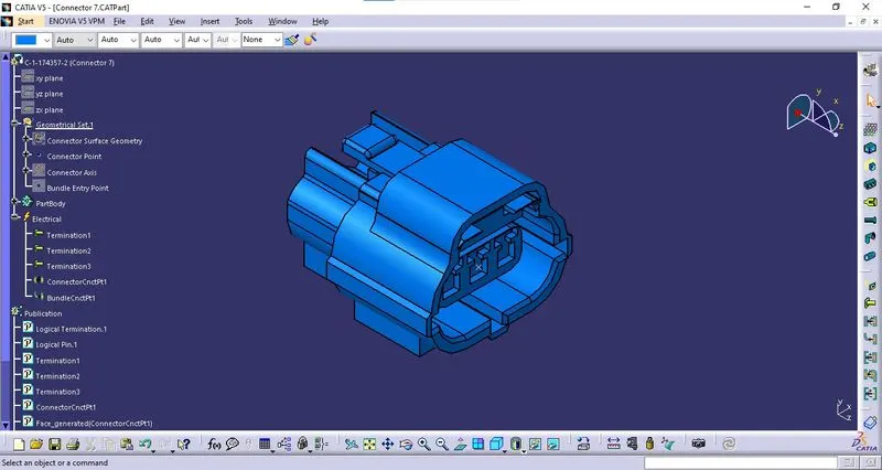
* Connector Axis: The connector axis is created with respect to Connector Point. 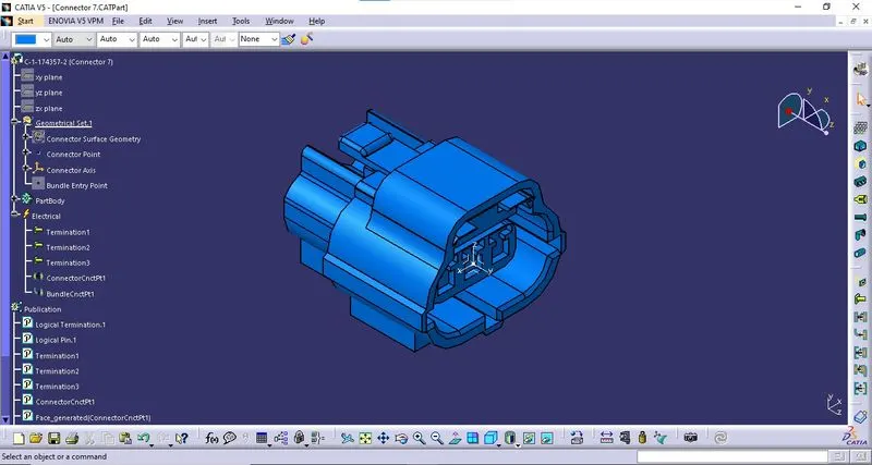
iii. Definition of Component:
The component is defined as the connector using "Define Connector" tab in the "Electrical Part Workbench". The number of terminals is defined.
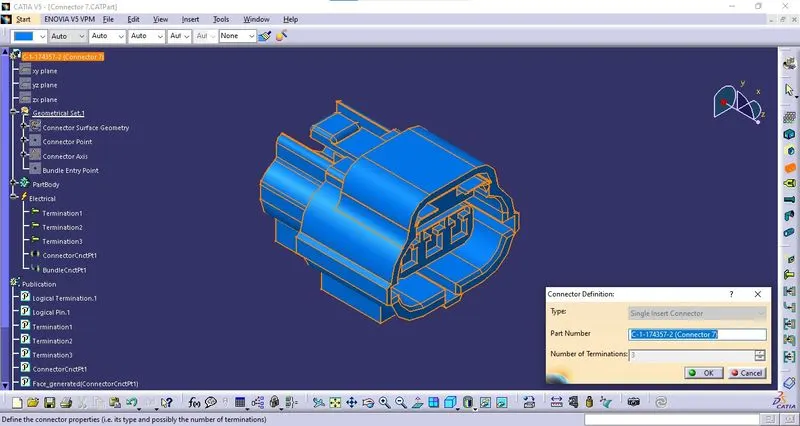
iv. Bundle Connection Point Definition:
The bundle connection point is defined using "Bundle Connection Point Definition" tab in the "Electrical Part Workbench". The parameters are defined appropriately. 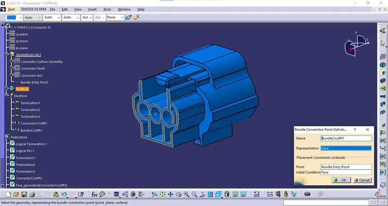
v. Connector Connection Point:
The connector connection point is defined using "Connector Connection Point Definition" tab in the "Electrical Part Workbench". The parameters are defined appropriately. 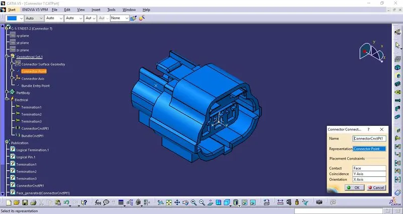
8. C-DT06-08SA-CE01 - Connector 8:
i. Download 3D Part: The 3D model is downloaded from the given link and saved as a Catpart file. 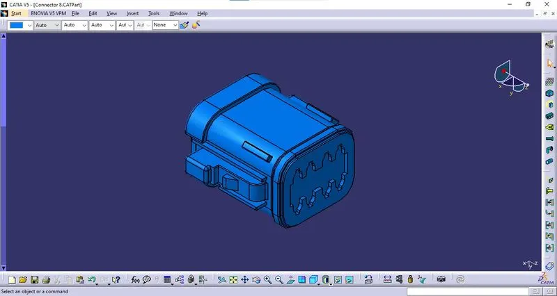
ii. Geometrical Parameters:
* Bundle Entry Point: The bundle entry Point is created at the rear part of the connector. 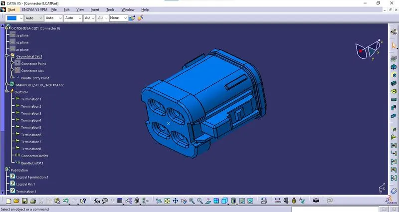
* Connector Point: The connector Point is created at the mating side of the connector. 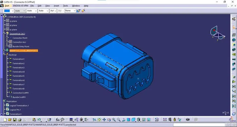
* Connector Axis: The connector axis is created with respect to Connector Point. 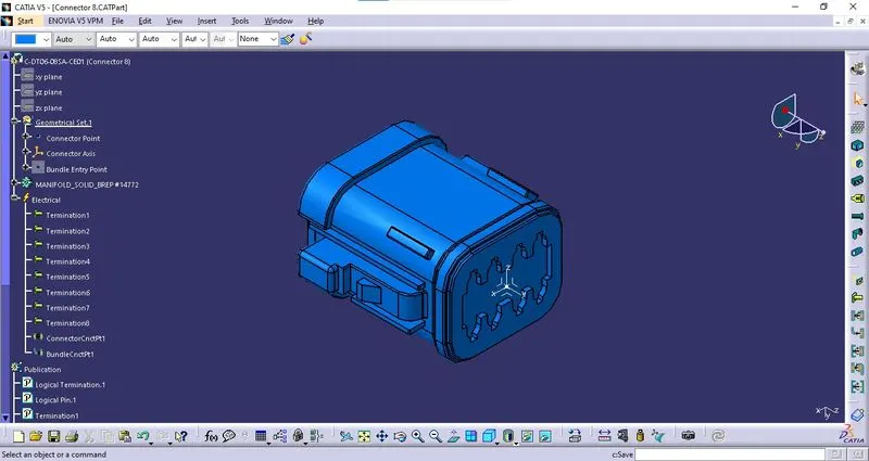
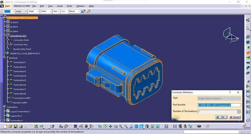
iii. Definition of Component:
The component is defined as the connector using "Define Connector" tab in the "Electrical Part Workbench". The number of terminals is defined.
iv. Bundle Connection Point Definition:
The bundle connection point is defined using "Bundle Connection Point Definition" tab in the "Electrical Part Workbench". The parameters are defined appropriately. 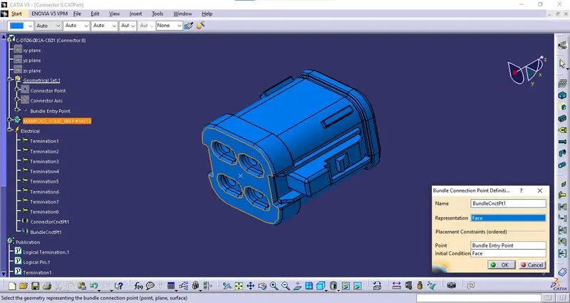
v. Connector Connection Point:
The connector connection point is defined using "Connector Connection Point Definition" tab in the "Electrical Part Workbench". The parameters are defined appropriately. 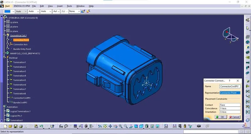
9. C-DT06-08SA-EP07 - Connector 9:
i. Download 3D Part: The 3D model is downloaded from the given link and saved as a Catpart file. 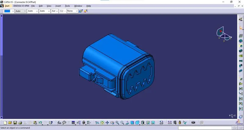
ii. Geometrical Parameters:
* Bundle Entry Point: The bundle entry Point is created at the rear part of the connector. 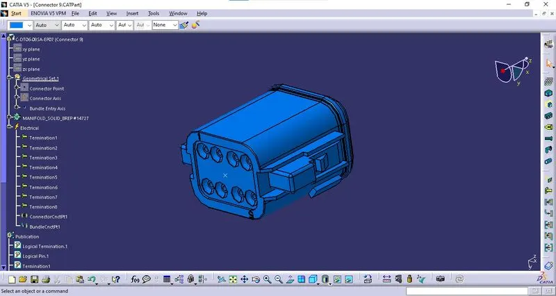
* Connector Point: The connector Point is created at the mating side of the connector. 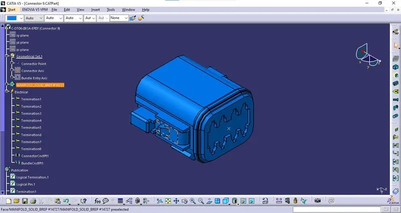
* Connector Axis: The connector axis is created with respect to Connector Point. 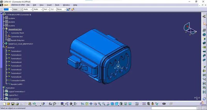
iii. Definition of Component:
The component is defined as the connector using "Define Connector" tab in the "Electrical Part Workbench". The number of terminals is defined.
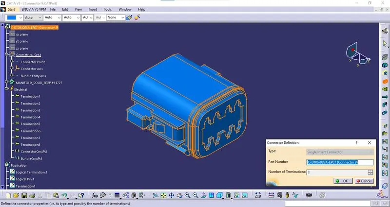
iv. Bundle Connection Point Definition:
The bundle connection point is defined using "Bundle Connection Point Definition" tab in the "Electrical Part Workbench". The parameters are defined appropriately. 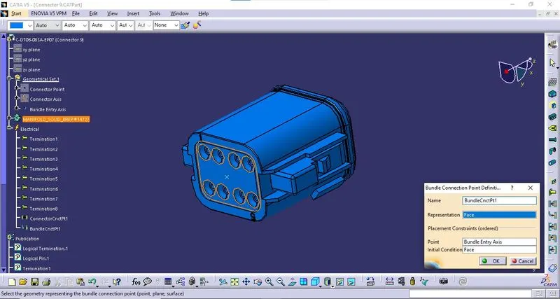
v. Connector Connection Point:
The connector connection point is defined using "Connector Connection Point Definition" tab in the "Electrical Part Workbench". The parameters are defined appropriately. 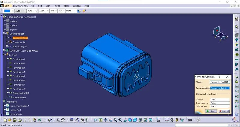
10. C-YDTS26F15-35SNV001 - Connector 10:
i. Download 3D Part: The 3D model is downloaded from the given link and saved as a Catpart file. 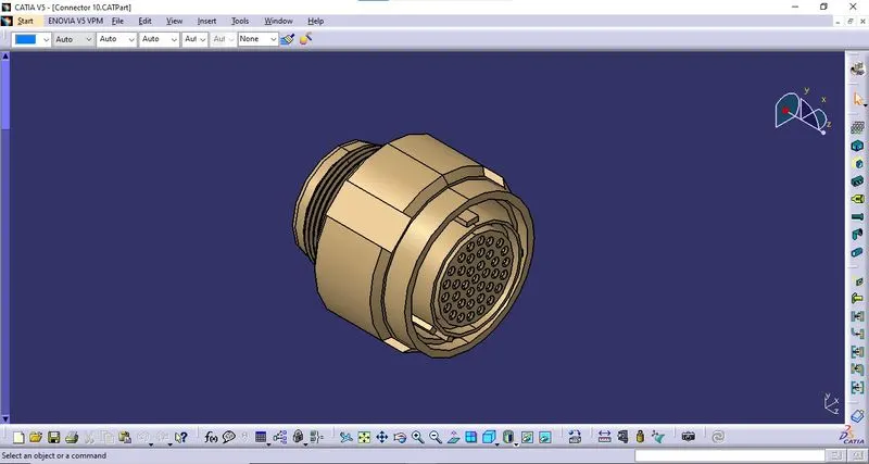
ii. Geometrical Parameters:
* Bundle Entry Point: The bundle entry Point is created at the rear part of the connector. 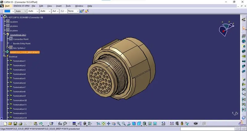
* Connector Point: The connector Point is created at the mating side of the connector. 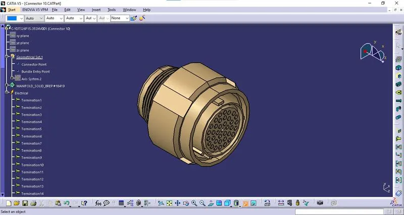
* Connector Axis: The connector axis is created with respect to Connector Point. 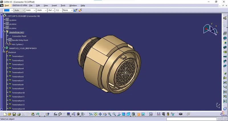
iii. Definition of Component:
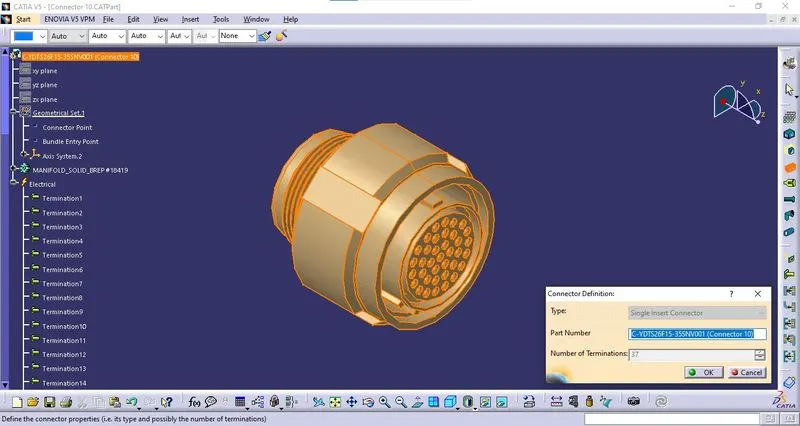
The component is defined as the connector using "Define Connector" tab in the "Electrical Part Workbench". The number of terminals is defined.
iv. Bundle Connection Point Definition:
The bundle connection point is defined using "Bundle Connection Point Definition" tab in the "Electrical Part Workbench". The parameters are defined appropriately. 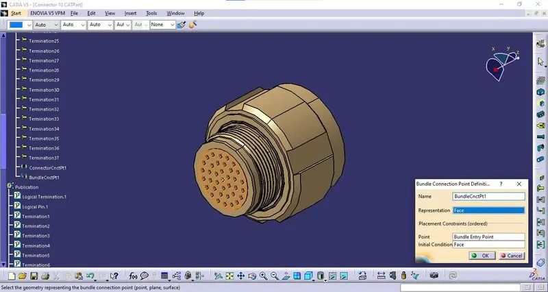
v. Connector Connection Point:
The connector connection point is defined using "Connector Connection Point Definition" tab in the "Electrical Part Workbench". The parameters are defined appropriately. 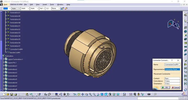
WIRING HARNESS ASSEMBLIES:
Harness A:
i. Create Product File:
A new Product file is created with "Harness A" as file name.
ii. Create a Sub-Product File:
A new product file is created into the above-created product file by right click on "Harness A"Product file > Components > New Product. The file is named "Assy. Geometrical Bundle A".
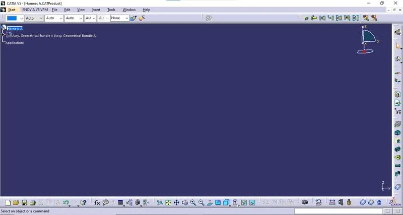
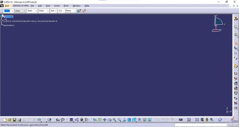
iii. Define Sub-Product Electrically:
The created Sub-Product is defined electrically by using the "Geometrical Bundle" option from the "Wiring Harness Assembly" workbench.
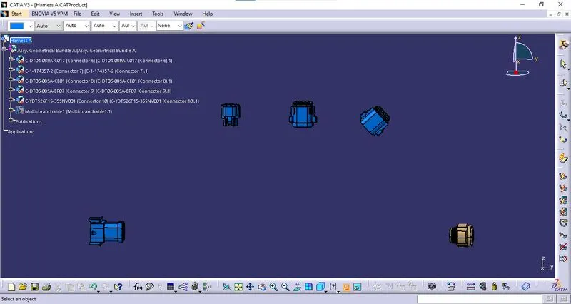
iv. Import & Locate Components:
All the required components as per the wiring diagram provided are imported into the "Geometrical Bundle" using the "Existing Component" option from the "Assembly" workbench.
The imported components are located at the correct location and orientation as per the requirement provided in the wiring diagram.
v. Creating Wiring Harness:
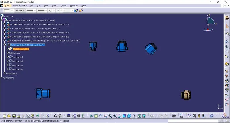
The multi-branchable part is created by using the "Multi-Branchable Document" option from the "Wiring Harness Assembly" workbench.
* Branchable 1:
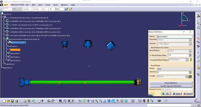
Branchable 1 is created between Connector 6 and Connector 10 with a bundle diameter of 15mm and a bend ratio of 1.4.
*Branchable 2:
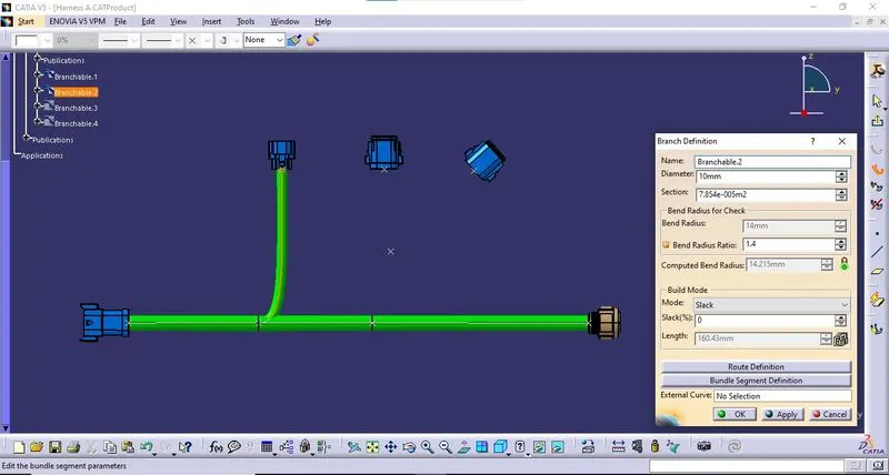
As per the diagram, in Branchable 1, Branch point 1 is inserted at a specific location by using "Add Branch Point" option.
Branchable 2 was created in between Branch point 1 and Connector 7 with a bundle diameter of 10mm and a bend ratio of 1.4.
*Branchable 3:
As per the diagram, in Branchable 1, A Branch point 2 is inserted at a specific location by using "Add Branch Point" option.
Branchable 3 was created in between the Branch point 2 and Connector 8 with a bundle diameter of 10mm and a bend ratio of 1.4.
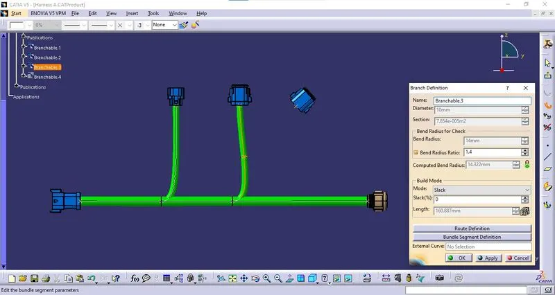
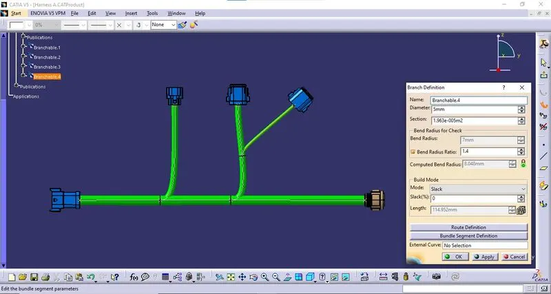
*Branchable 4:
As per the diagram, in Branchable 3, A Branch point 3 is inserted at a specific location by using "Add Branch Point" option.
Branchable 4 was created in between the Branch point 3 and Connector 9 with a bundle diameter of 5mm and a bend ratio of 1.4.
viii. Save the File:
The above-said product file is saved using the "Save Management" Option. All the required parts and product files are saved at a defined location.
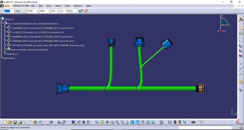
OUTPUT - WIRING HARNESS A ASSEMBLY:
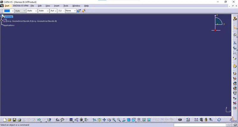
Harness B:
i. Create Product File:
A new Product file is created with "Harness B" as the file name.
ii. Create a Sub-Product File:
A new product file is created into the above-created product file by right click on "Harness A"Product file > Components > New Product. The file is named "Assy. Geometrical Bundle B".
iii. Define Sub-Product Electrically:
The created Sub-Product is defined electrically by using the "Geometrical Bundle" option from the "Wiring Harness Assembly" workbench.
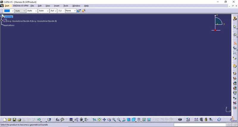
iv. Import & Locate Components:
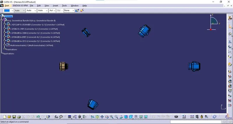
All the required components as per the wiring diagram provided are imported into the "Geometrical Bundle" using the "Existing Component" option from the "Assembly" workbench.
The imported components are located at the correct location and orientation as per the requirement provided in the wiring diagram.
v. Creating Wiring Harness:
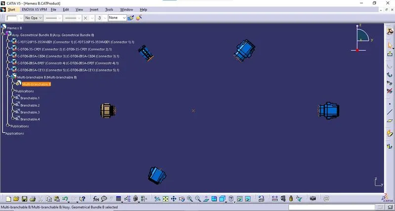
The multi-branchable part is created by using the "Multi-Branchable Document" option from the "Wiring Harness Assembly" workbench.
* Branchable 1:
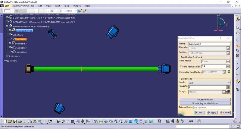
Branchable 1 is created between Connector 1 and Connector 5 with a bundle diameter of 15mm and a bend ratio of 1.4.
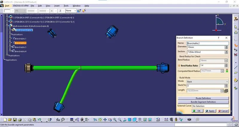
*Branchable 2:
As per the diagram, in Branchable 1, Branch point 1 is inserted at a specific location by using "Add Branch Point" option.
Branchable 2 was created in between Branch point 1 and Connector 4 with a bundle diameter of 10mm and a bend ratio of 1.4.
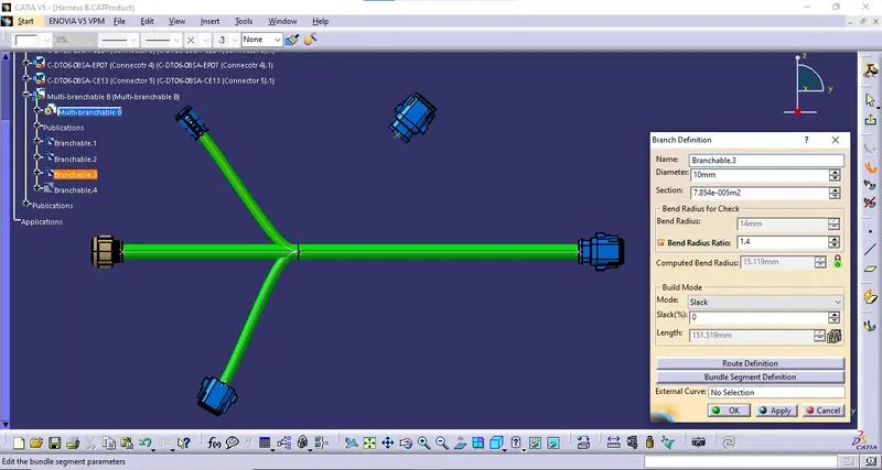
*Branchable 3:
Branchable 3 was created in between Branch point 1 and Connector 2 with a bundle diameter of 10mm and a bend ratio of 1.4.
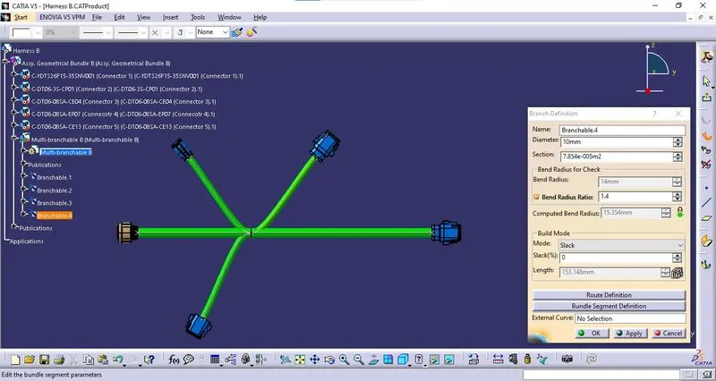
*Branchable 4:
Branchable 4 was created in between Branch point 1 and Connector 3 with a bundle diameter of 10mm and a bend ratio of 1.4.
viii. Save the File:
The above-said product file is saved using the "Save Management" Option. All the required parts and product files are saved at a defined location.
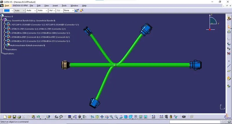
OUTPUT - WIRING HARNESS B ASSEMBLY:
CONNECTING BOTH WIRING HARNESS A & B TOGETHER ELECTRICALLY:
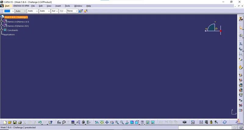
i. Create Product File:
A new Product file is created with the appropriate file name.
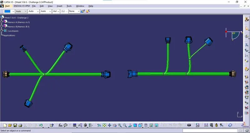
ii. Import Harnesses:
Both Harness A & Harness B are imported into the product file by copy-paste method.
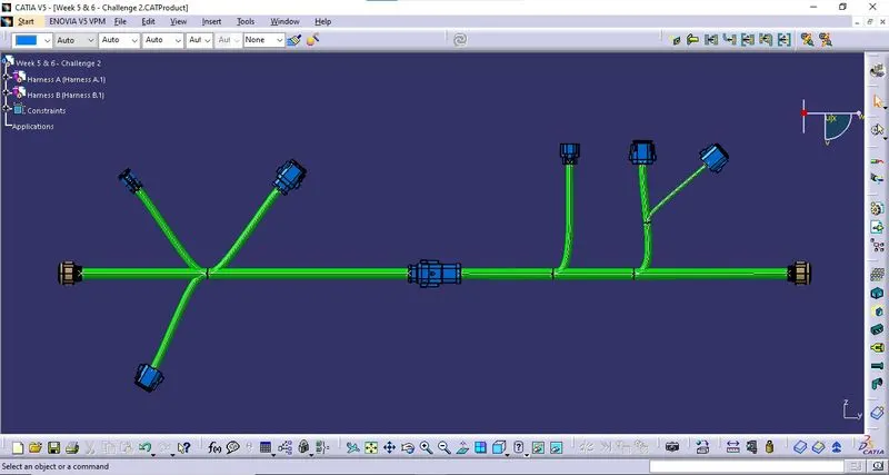
iii. Connect Harnesses Electrically:
Both the harnesses are connected electrically by using the "Connect Electrical Design" command in the"Harness Assembly Design" workbench connecting Connector 5 & Connector 6.
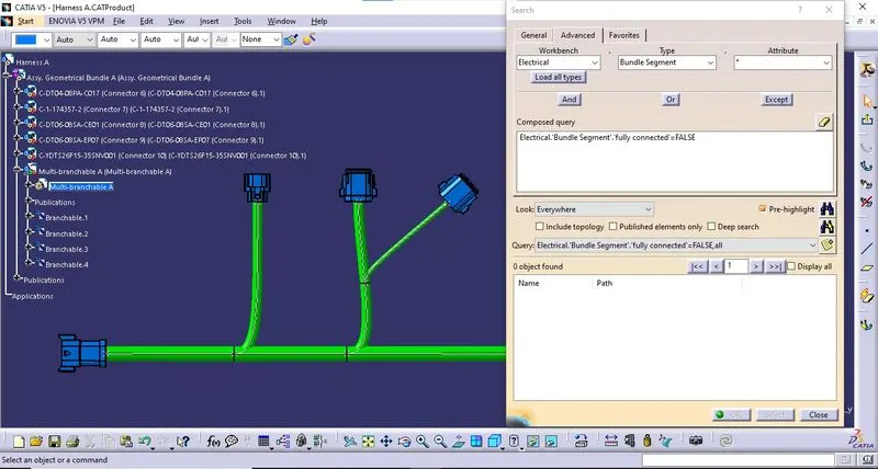
1. BUNDLE CONTINUITY:
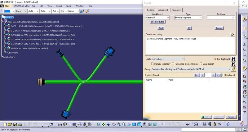
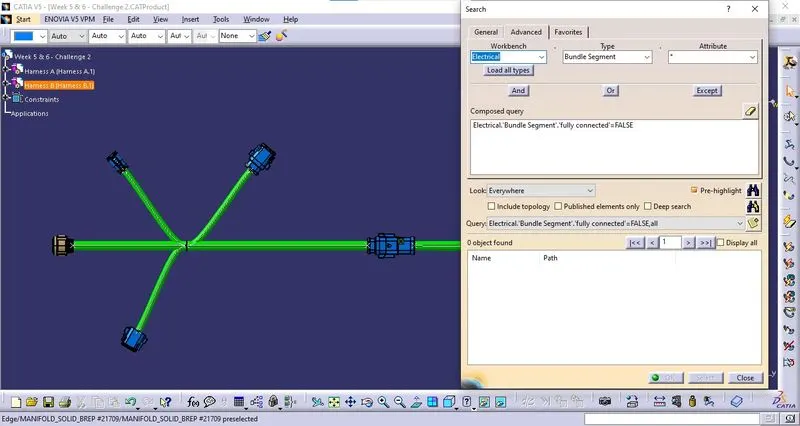
The Bundle Continuity is checked by the following method.
i. Select Edit > Search. The search window will open.
ii. In the search window, select the "Advanced" tab.
iii. In the Advanced window, In the workbench drop-down, select "Electrical", In the Type drop-down, select "Bundle Segment", In the Attribute drop-down, select "Fully Connected"
iv. In the Attribute Criterion dialog box, select "False" from the drop-down and click "Ok".
v. Click on the "Search" Icon from the next window.
vi. If there are no entries in the Query table, The bundle is fully connected.
Bundle Continuity - Harness A:
Bundle Continuity - Harness B:
Bundle Continuity - Electrically connected Harness Assembly:
2. 3D ANNOTATIONS:
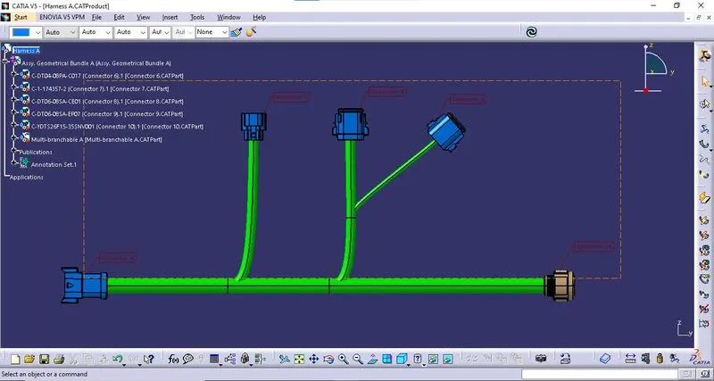
Harness A - Annotations:
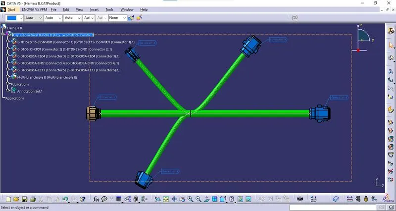
Harness B - Annotations:
Electrically connected Harness Assembly - Annotations:
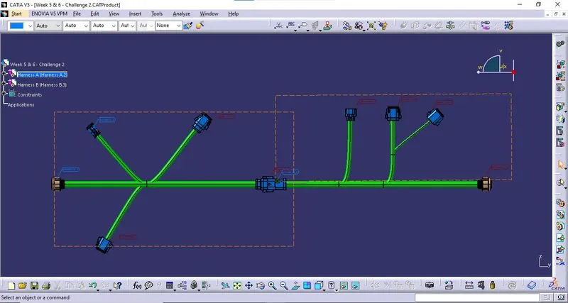
3. BUNDLE WARNING:
The below-found bundle warnings are shown while creating bundles. The required necessary actions were taken to correct them.
i. Tangency Issue:
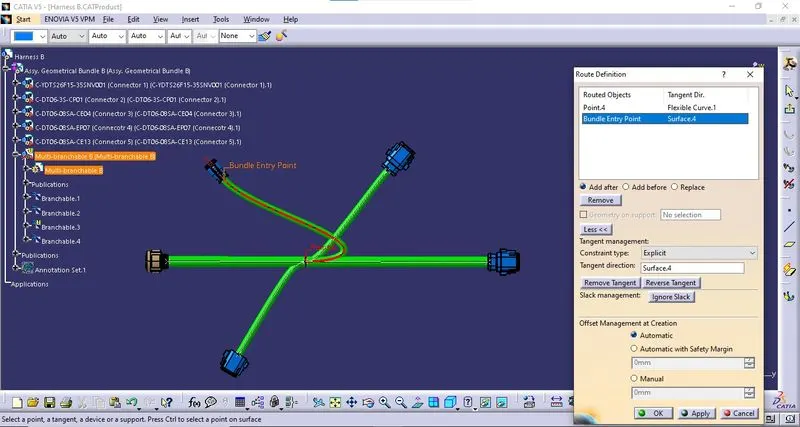
Reason: The tangency at point 4 was in the opposite direction.
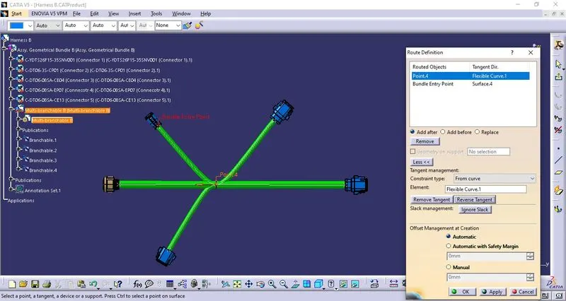
Solution: The tangency at point 4 was reversed by clicking on the "Reverse Tangent" tab.
ii. Length Issue:
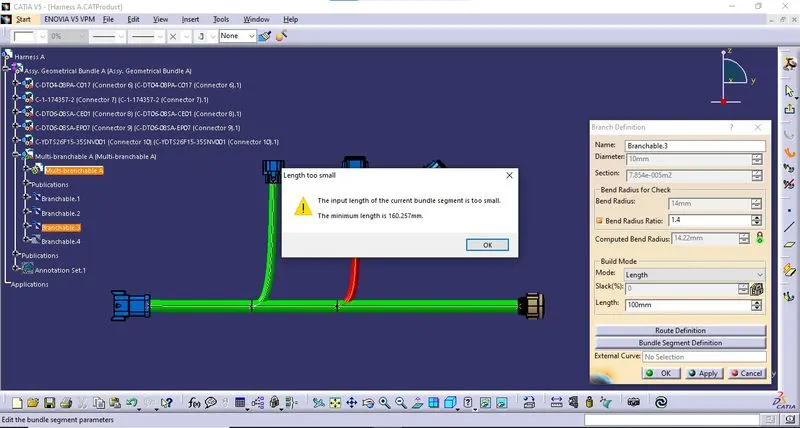
Reason: This occurs when the length of the bundle segment given is not sufficient to connect the routes.
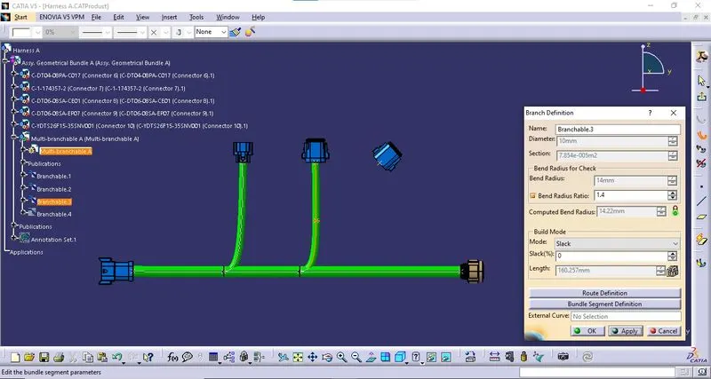
Solution: The sufficient length was given.
iii. Slackness Issue:
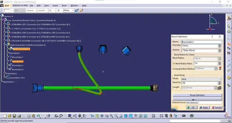
Reason: This occurs when the slackness is higher or lower than the acceptable limit.
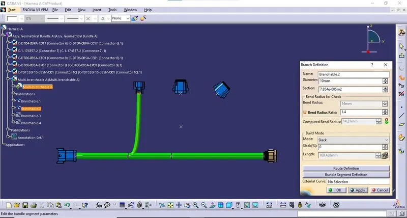
Solution: Slackness is adjusted to the optimal limit.
iv. Bend Radius Issue:
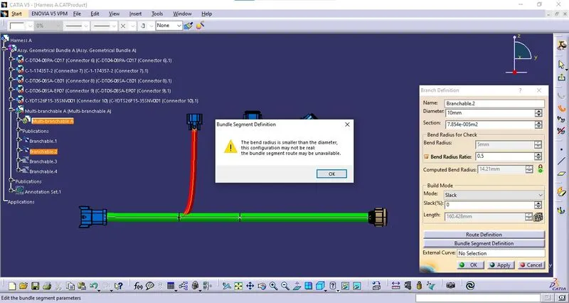
Reason: This occurs when the bend radius is not sufficient.
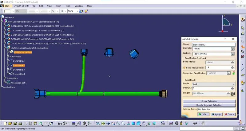
Solution: Optimal bend radius is provided.
4. SAVING ASSEMBLY IN .CATPart AND .igs:
i. Saving as CATPart file.
The product file is saved as CATPart by selecting Tools > Generate CATPart from the product in the Mechanical Assembly Design Workbench. A new Part file will be created.
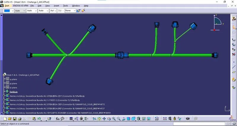
Save the file with an appropriate name.
ii. Converting to .igs format:
The created part file can be converted into .igs format by selecting File > Save As. Select .igs from the Save AS Type drop-down.
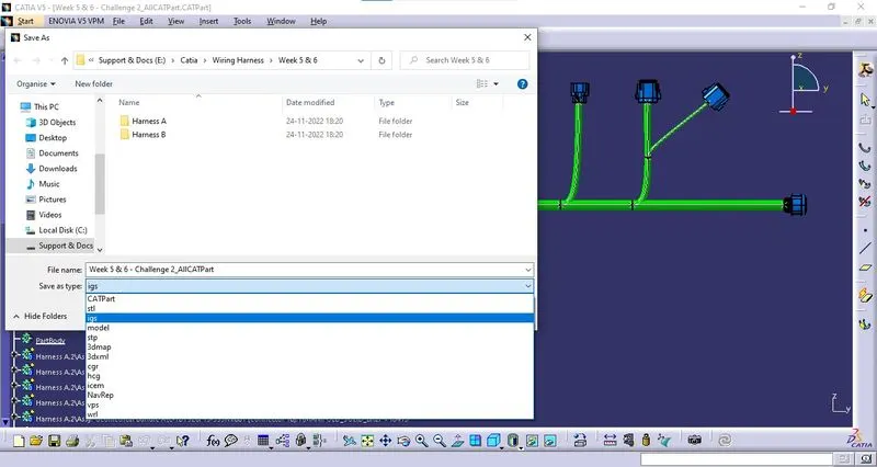
Thus the part file is converted into .igs format.
ATTACHMENTS:
All the Part files and product files along with the part files of the components used in this assembly are attached as a single compressed file.