Week 8 - Challenge 2 - Switch Bezel Design
Input:
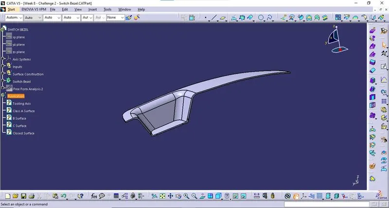
The input was given as Class A surface.
Tooling Axis:
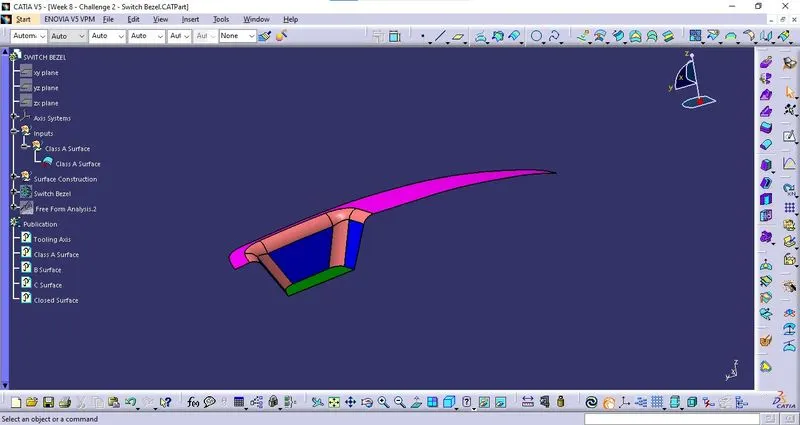
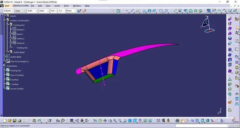
The tooling axis was created using Sketch. A point was created as normal with respect to the base of the handle cavity in the class A surface. A positioned sketch was created in YZ plane and point projection at the point we created. With reference to the 3D projection in the sketch view, a bisecting line was created. Another positioned sketch was created in XZ plane and point projection at the point created, With reference to the boundaries of the 3D projection, a parallel line was drawn at 6-degree angle from the boundary. The bisecting line was drawn in between the lines from both XZ and YZ planes. This line is the Tooling Axis.
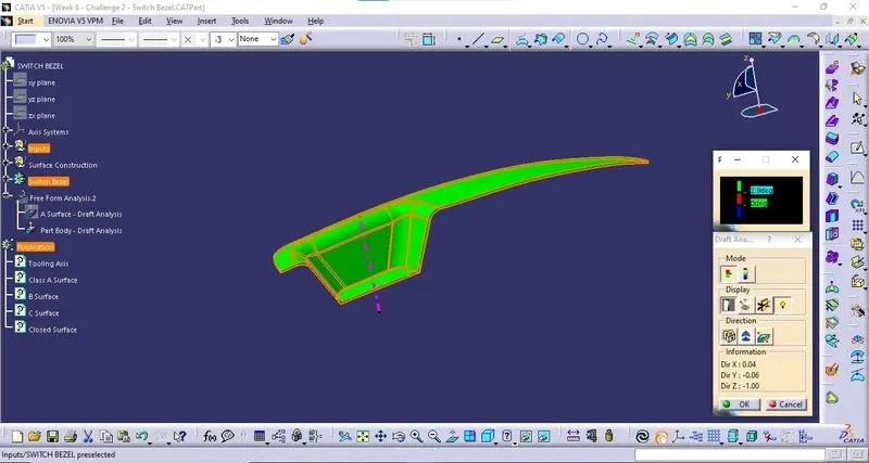
Draft Analysis of Class A:
Draft analysis is done on the Class A Surface with respect to the Tooling Axis created.
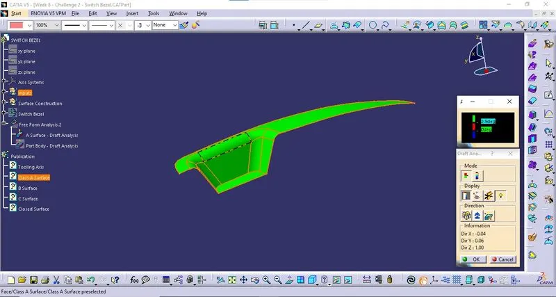
The minimum draft angle was given as 2.9 Degrees.
Class B Surface:
Class B was created by simplifying the faces of the Class A Surface by dividing them into multiple small sets. Such created sets are offset to the thickness of the component, (i.e.) 2.5 mm. Finally, these sets are trimmed together to achieve the desired class B Surface. The commands used here are Untrim, Extrapolate, Trim, and Offset.
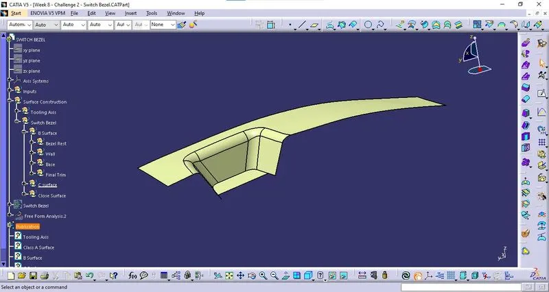
Class C Surface:
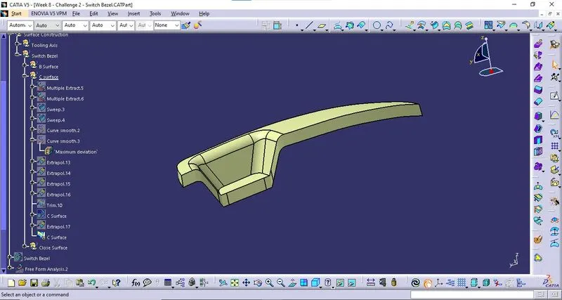
The boundary is created from the Class A surface and it is extended along the Z direction using the Sweep command with the created boundary as the Guide Curve and Tooling axis as the reference direction, Sweep is done in the appropriate direction for every boundary. The Class A surface is joined along with the created Sweeps. And thus the Class C Surface is created.
Closed Surface:
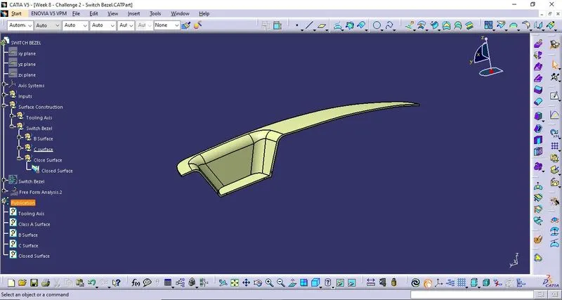
In the final stage of the surface creation, The Class A Surface and Class B Surface are trimmed together to form an appropriate closed surface.
Part Body - Switch Bezel:
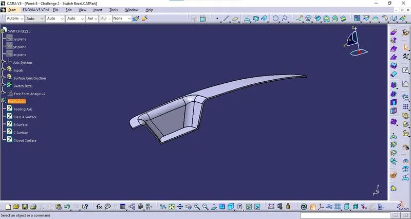
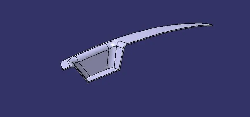
The part body is created using the close Surface command in Part Workbench with Closed Surface as the reference surface.
Isometric View:
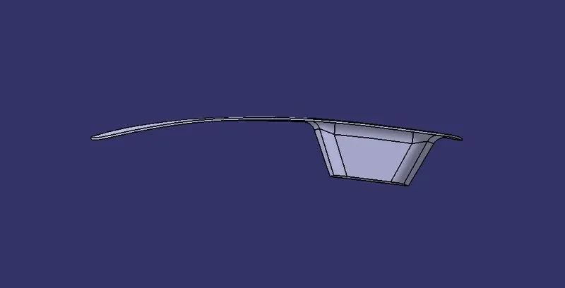
Front View:
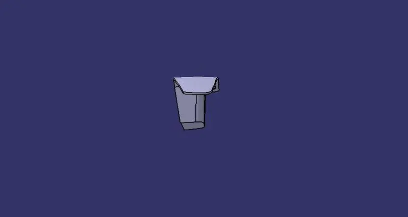
Side View:
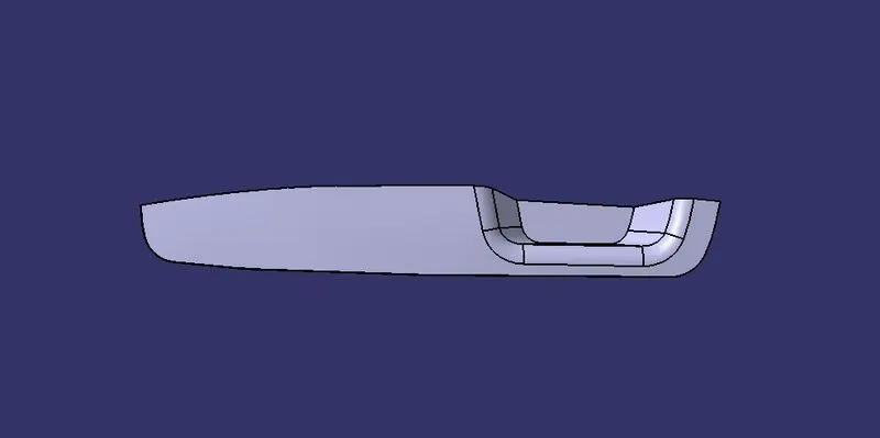
Top View:
Draft analysis of the Component:
Draft analysis is done on the Component with respect to the Tooling Axis created.
The minimum draft angle was given as 2.9 Degrees.
Publication:
During this process of designing the base plate, The Objects which are used frequently are published for ease of operation. Published Objects are,
- A Surface.
- Tooling Axis
- B Surface
- C Surface
- Closed Surface