Wiring harness design in CATIA V5 - 3D modeling Week 5 & 6 Challenge
- Open catia v5 assembly work bench
- Then create two new products in a single product named Harness A and Harness B
- Import given connectors to respective Harness A and Harness B
- Then arrange them as per the given positions by manipulation and constraints
- same for the both Harnesses
- Interconnection made for the Harness A and Harness B
- Then change work bench to electrical wire harness
- And connectors are set to bundle connection point
- Required bundle segments are made for providing branches
- Then check for the bundle discontinuties
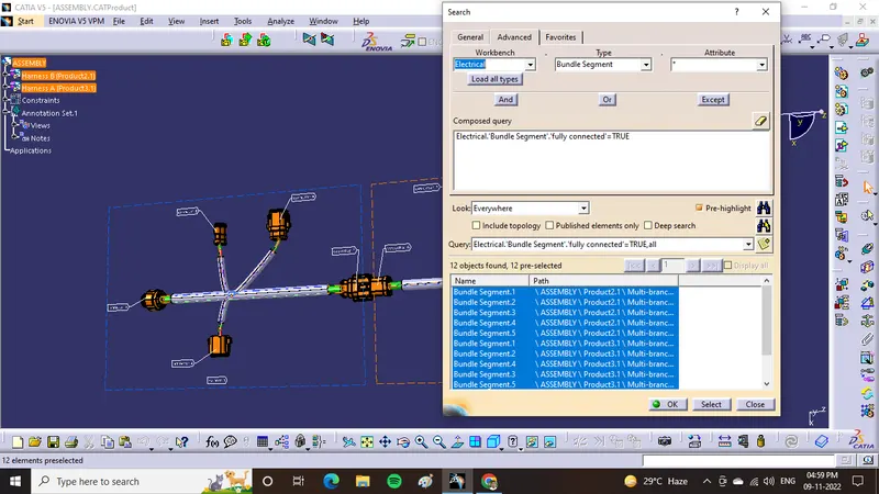
- In the above image it is shown bundle is checked for trueness of continuity and it passed
- Then add annotations by using lable command for connectors 1,2,3,4,5,6,7,8,9,10. and lable Harness A and Harness B.
- Then assembly file converted to .catpart by using generate cat part from product option in tools.