Wiring harness design in CATIA V5 - 3D modeling Week 5 & 6 Challenge
Layout of the Harness for Routing
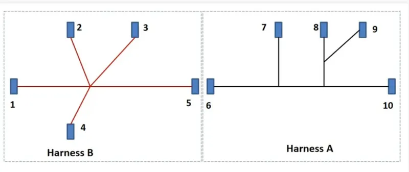
- Downloded all the required connectors for this routing and saved the CATpart.
- provided all the electrical definitions for the connectors.
- And using store device command, stored all the connectors to the connectors catalogue.
Details of connectors used as per the given data.
- YDTS26F15-35SNV001
- C-DT06-3SCP01
- C-DT06-08SA-CE04
- C-DT06-08SA-EP07
- C-DT06-08SA-CE13
- C-DT04-08PA-C017
- C-1-174357-2-E
- C-DT06-08SA-CE01
- C-DT06-08SA-EP07
- YDTS26F15-35SNV001
- Using first 5 connectors created the Harness_B CATProduct file.
- All the five connectors are placed as per the layout using manipulation and compass.
- Using geometrical bundle command provided in electrical harness assembly workbench, electrically defined the assembly.
- new part is created using multi-branchable document command.
- Then goto branch definition command provided required data in the tab opened(diameter, slack%, bend radius etc.)
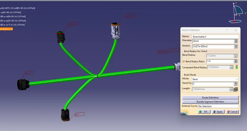
- Above shown figure has the branch definition tab.
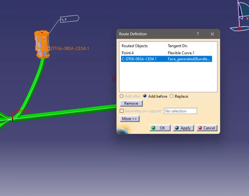
- From the branch definition tab goto route definition.
- There we have the choice to select the routing objects, we can select the connecters or branch points to route.
- Below figure shows the route definition tab. Here the routed objects are an added branch point and a connector.
- Similarly the routing is done for the Harness_A and saved both CATProduct files.
- Both Harness_A and Harness_B files are added to a newly created Product file named 'Assy_Wiring_Harness_Context'.
- Before that a rough annotations are provided for the connectors. This option is available in mechanical assembly work bench. Here I have used 'flag note with leader' command for the annotation.
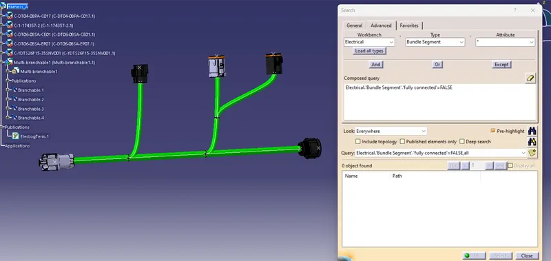
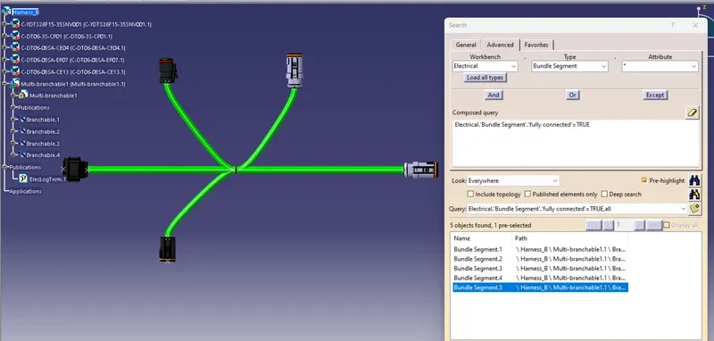
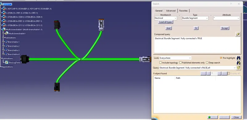
- Also checked the Bundle continuity, For bundle contiuity checking; Edit > Search > advanced
- select electrical from the workbench dropdown list
- select bundle segment as type.
- select fully connected as attribute.
- we choose the Query as true or false.
- if we select true- it will shows all the bundles that are connected and wise versa. All related figures are given below.
Snap of Bundle Continuity Checking of Harness_A
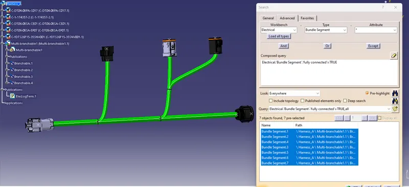
Snap of Bundle COntinuity checking of Harness_B
Snaps after Giving Annotations
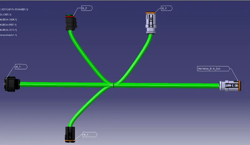
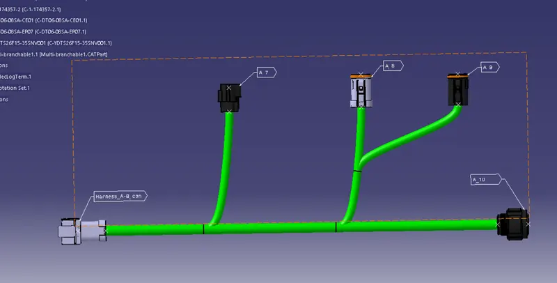
- After adding Harness_A and B to the new product file jump to electrical assembly design workbench.
- Then using the command 'connect electrical devices' We can connect both harnesses together. The respective figures are given below.
Harness_A and Harness_B INTER-Connection
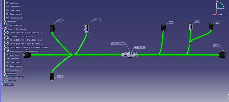
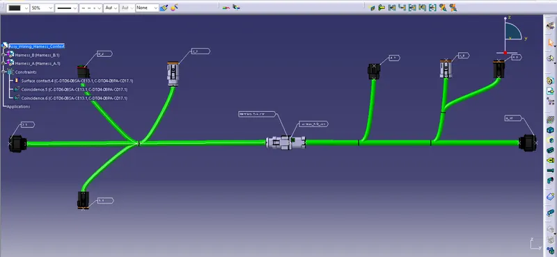
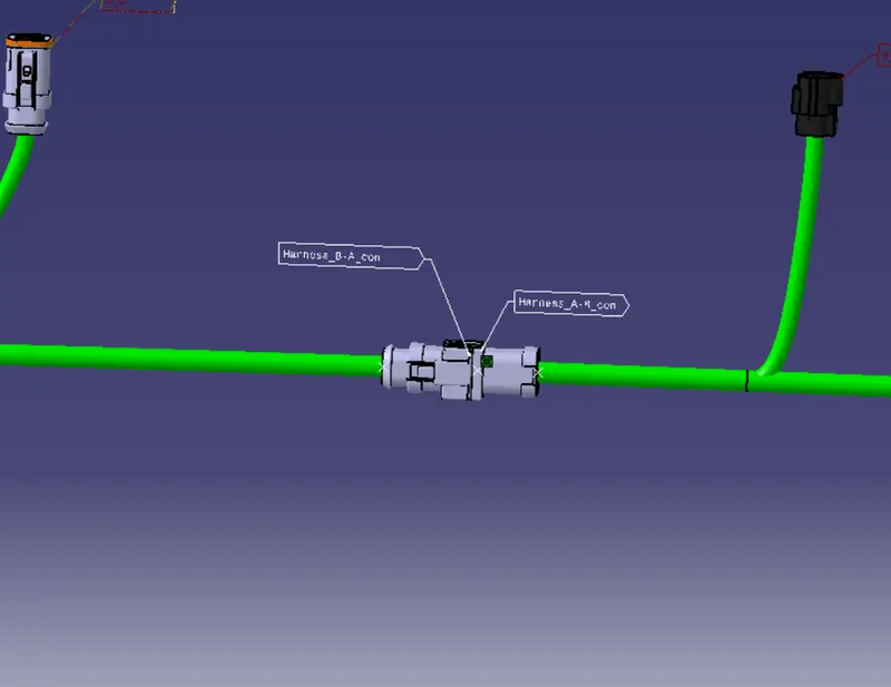
- For creating igs file format we have to save this assembly as CATpart.
- igs files can open in many other softwares if we needed, but the CATpart and CATProduct files are cannot support on the other CAD softwares.
- So for creating the igs file first we have to save this assembly as CATPart.
- For that we have an option in tools 'generate CATPart from Product', This option is available in mechanical assembly workbench
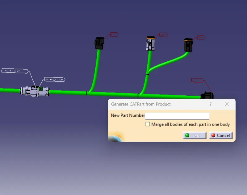
- We can select the product file that have to save as CATPart and click ok
Snap of whole assembly after converting to CATpart
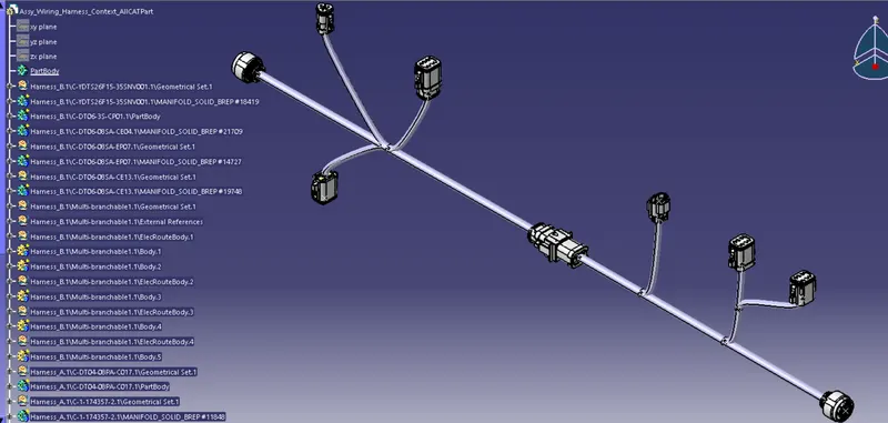
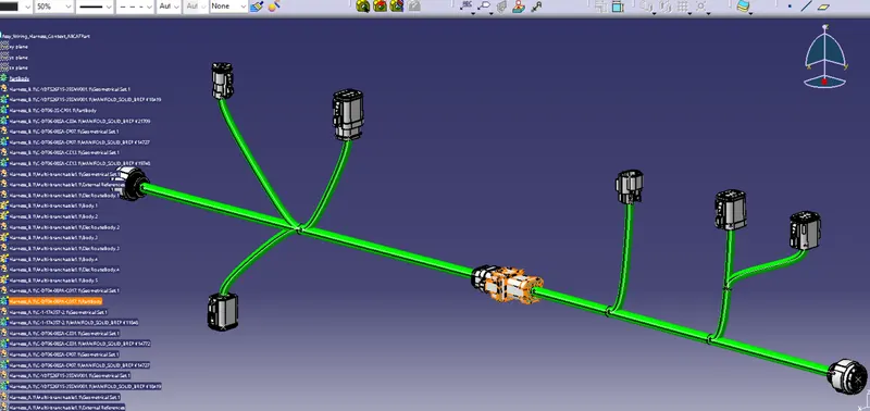
- All the CATPart, CATProduct, Connectors catalogue and igs files are attached.