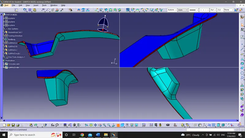
Week 8 - Challenge 2 - Switch Bezel Design
DRAFTING ANALYSIS
- Here the tooling axis is not in particular direction along the three axis, tooling axis creates angle with all the three axis(X,Y&Z).
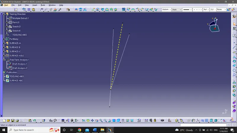
- Tooling axis is created by bisecting method of lines.
Tooling axis
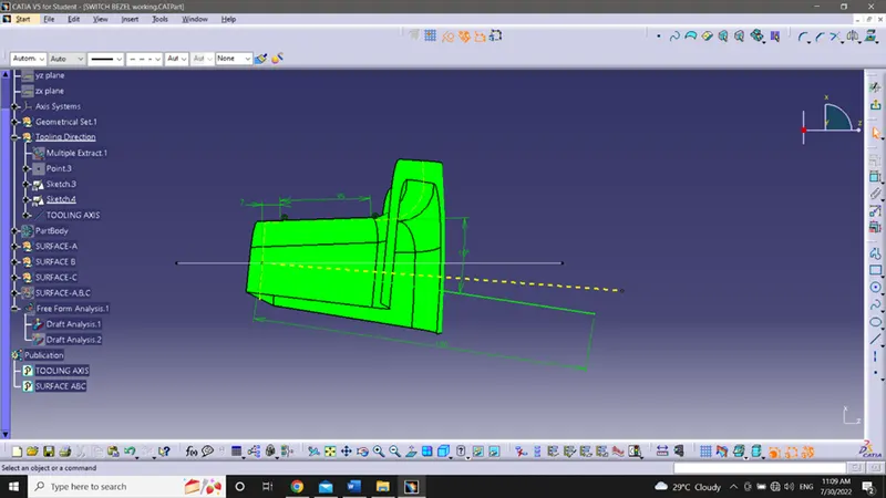
- First extracted a plane of the surface-A, and made a point on that plane centre.
- and inserted an axis system on that point.
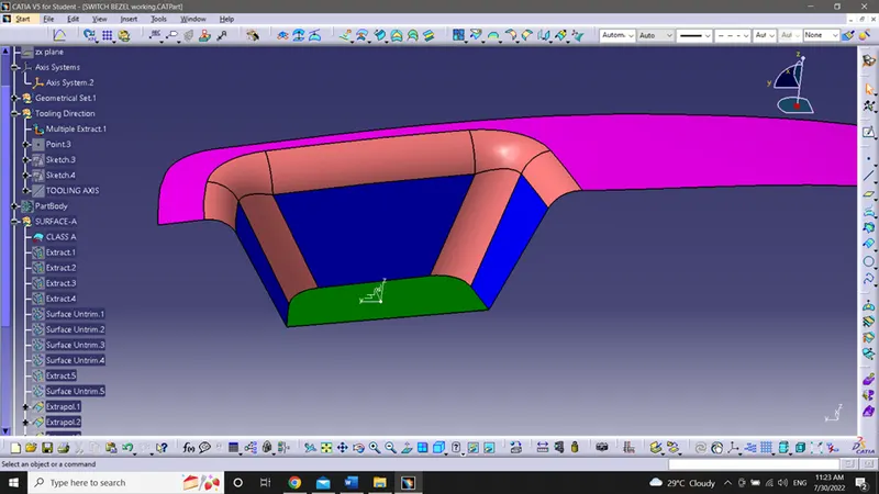
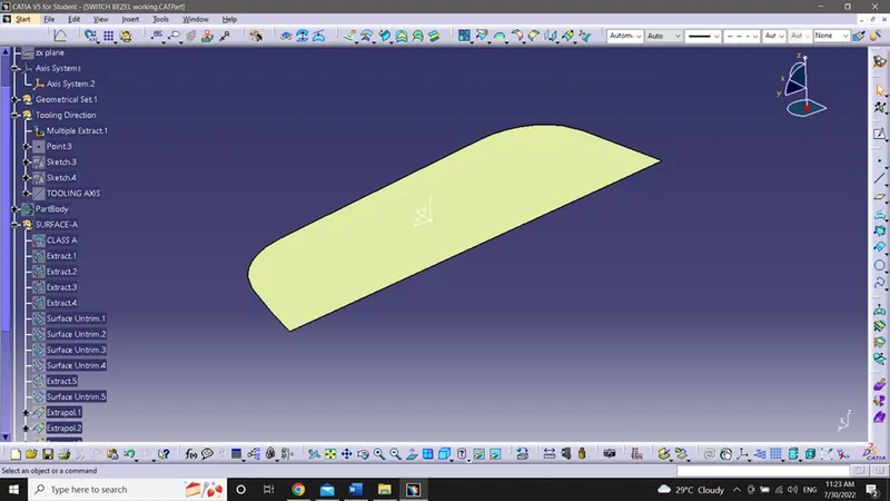
- Created a sketch on the new YZ-plane, made the Tooling axis on the YZ-plane using bisect line, with respect to the two lines created on the 2 walls of the surface-A.
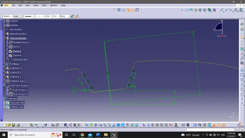
- And next we have to made tooling axis with respect to the other plane of the surface-A, on XZ-plane.
- But there we don't have 2 plane or line to create tooling axis using bisect line method, so we created a line on the same point making an angle greater than 3degree with the respecting plane profile.
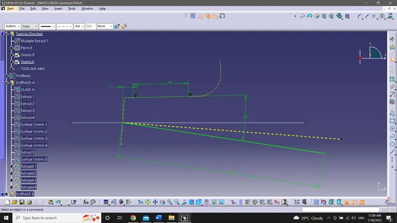
- And now we have 2 tooling axis on the two planes, using these 2 as reference we create our tooling axis for the drafting analysis.
- using bisect line type create a 3D line by giving two reference as the 2 tooling axises on the 2 planes.
Drafting Analysis os Surface-A
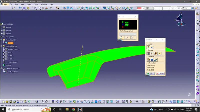
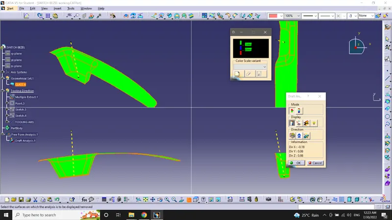
- green color implice angle greater than 3degree
- Red color implice negetive angle.
- Blue color implice angle between 0 and 3 degree.
Drafting analysis of solid body
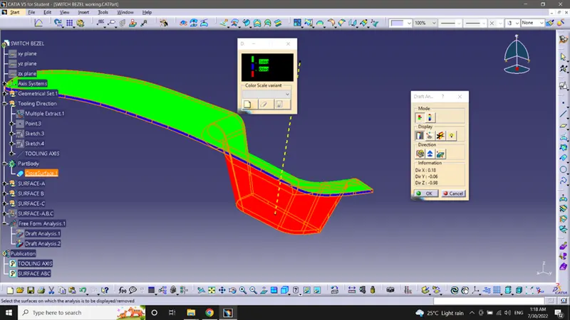
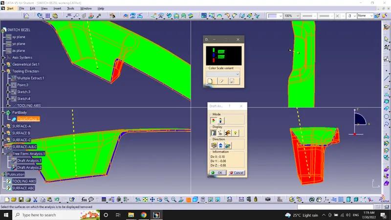
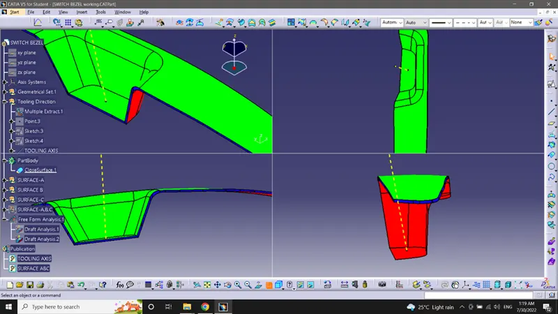
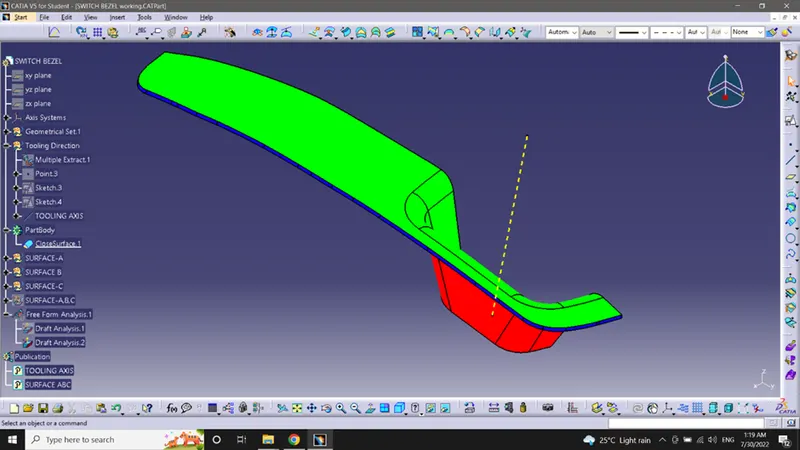
- Angle greater than 3 degree easy to eject from the mold, and negetive angle leads to tear and wear of the component.
Different views of the solid body.
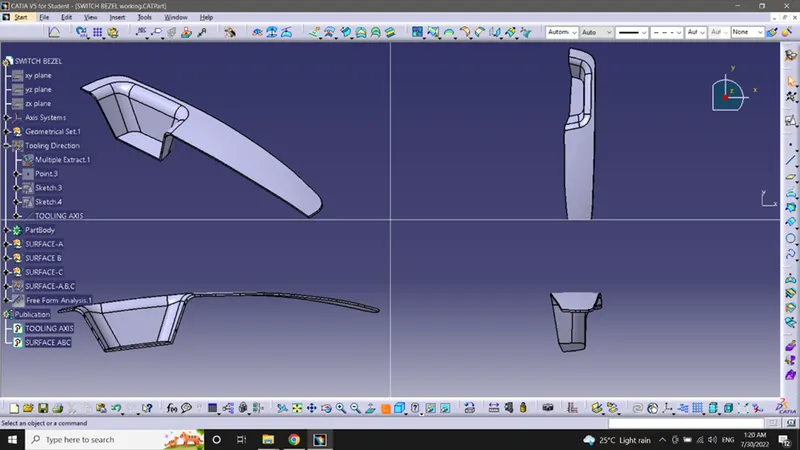
Surface-A,B,C