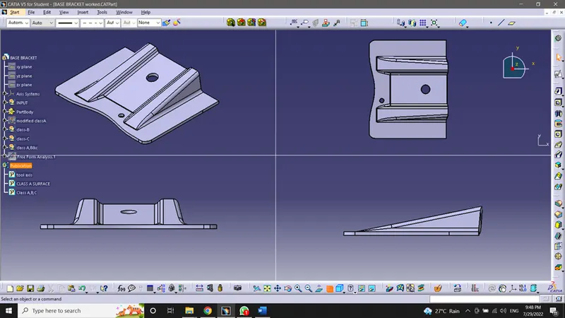
Week 8 - Challenge 1 - Base Bracket Design
Draft Analysis
- Here in this case the tooling axis is along vertical direction (along z-axis)
- Tooling axis is created by bisecting method.
- In this model we have a hole on the body, so we created the tooling axis reference to this hole.
Bisecting Method:
- created a point centre to the hole on the body centre.
- and made an axis system on this point.
- created an intersection line refernece to the YZ plane on the new axis system.
- using this intersect boundary vertexes as reference, we made two lines using point-point line type.
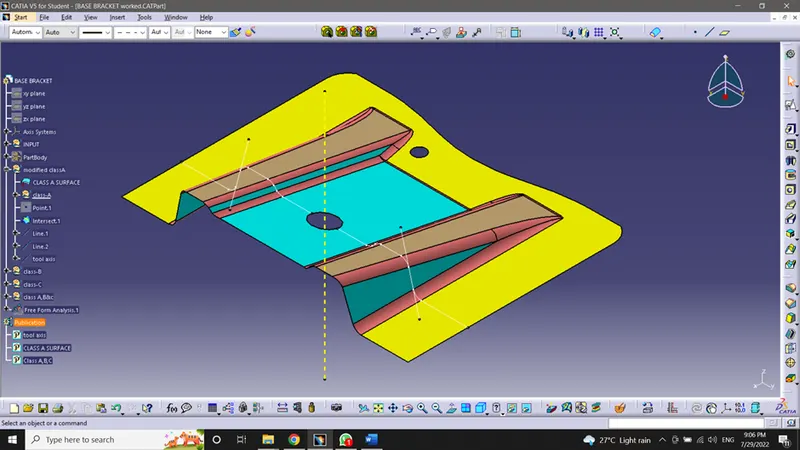
- above picture we can see the two extended lines on the intersect line.
- We create the toolling axis reference to these two lines.(bisectional relation).
- create a line using bisect line type reference to the two line we created earlier.
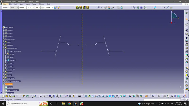
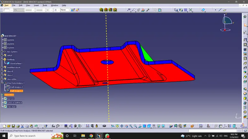
Pictures of Drfting Analysis with color code
Class-A surface drafting analysis
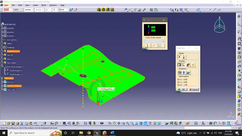
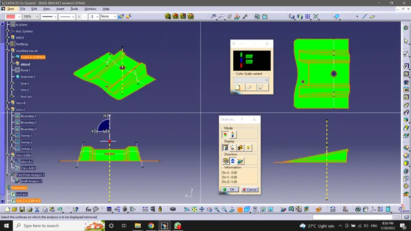
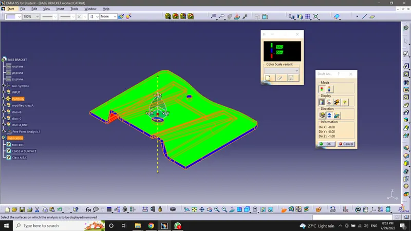
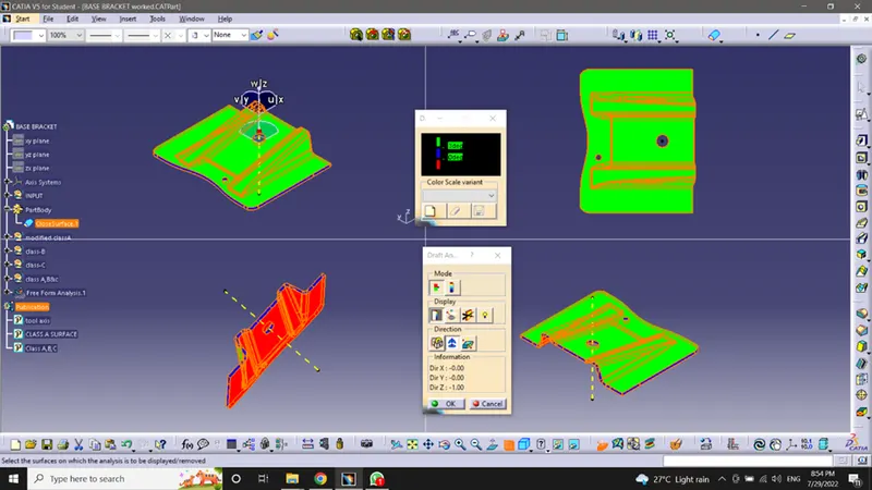
- The green color code implice the angle greater than 3degree, that is easy to eject, no tear and wear of the part.
- Red color code implice negetive angles that is less than 0 degree, difficult to eject.
- and blue is zero angle.
Solid body drafting Analysis
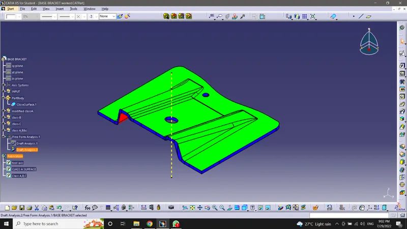
Final plastic body picture