Wiring harness design in CATIA V5 - 3D modeling Week 5 & 6 Challenge
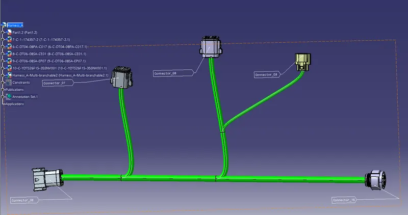
The Harness_A and the connectors of the Harness_A are electrically defined and also the wire routing of the Harness_A will be shown in the above-mentioned figure.
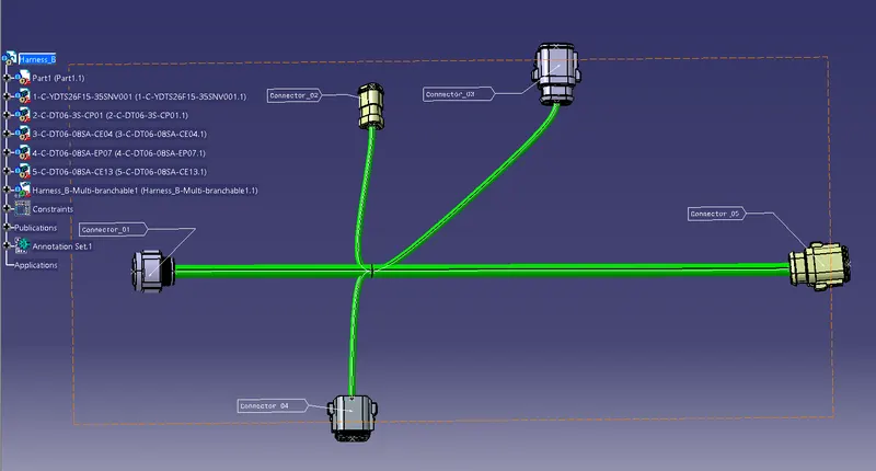
The Harness_B and the connectors of the Harness_B are electrically defined and also the wire routing of the Harness_B will be shown in the above-mentioned figure.
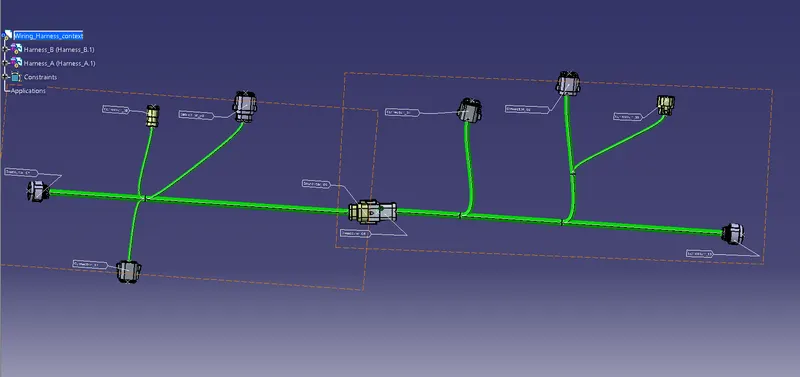
The Harness_A and Harness_B are assembled together to create the harness assembly.
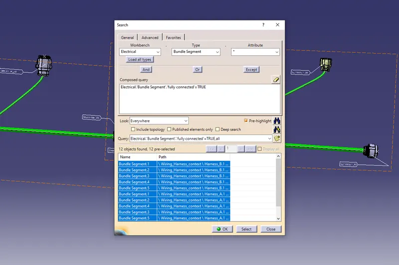
The above figure shows that the Bundle segments are fully connected.
The Given connectors are defined as connectors in the electrical workbench like the Bundle connection point and the connector connection point of the Harness_A the connectors are placed at some location in the given figure and defined as the geometrical bundle as well as the multi-branchable segment to the bundles to create the harness routing. The above mention method is followed by the Harness_B also. Next, connect the Harness_A and Harness_B in the interconnected connectors as shown in the given figure in the Electrical Assembly design workbench by using the connect electrical devices tool to connect the Harness_A and Harness_B in the Wiring_Harness_context assembly. There is no error in the bundle segment connection.