Project 1
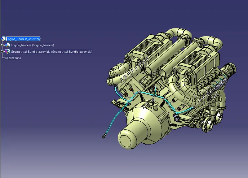
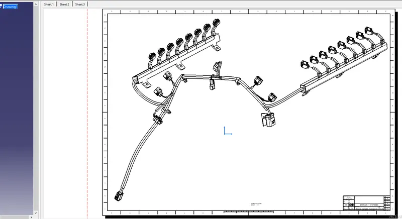
The required connectors and supports are electrically defined first. Then go to the new product file and get the engine part and import the required connectors and supports for the route harness like the camshaft sensor connector, coolant temperature sensor connector, etc.., and the supports like P clamp, L clip, and Fir tree clip, etc..,
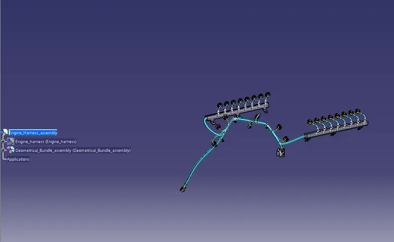
The connectors and supports are placed at the desired location, then they go to the electrical harness assembly workbench to create the routing of the engine harness. The Minimum space is available on the fuel injector side that's why we use the guiding channels in the engine harness.
The Packing rules are followed as per standards like the minimum distance between the connector and bundle branch point is 50mm. The type of packing rules is followed successfully. The engine is in a high-temperature zone that's why we are using the protective covering in high temperature withstands tubes or tapes will be applied in the engine harness assembly and I was using the nylon tape in the engine harness assembly.
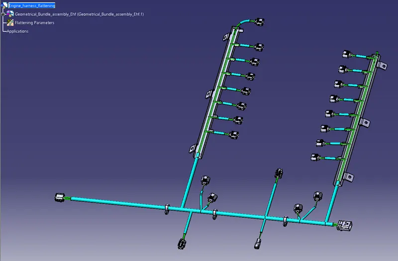
The Next step goes the new product, the electrical harness flattening workbench, and set the flattening parameters, extract the geometrical harness bundle of the engine harness assembly, then flatten the harness bundle.
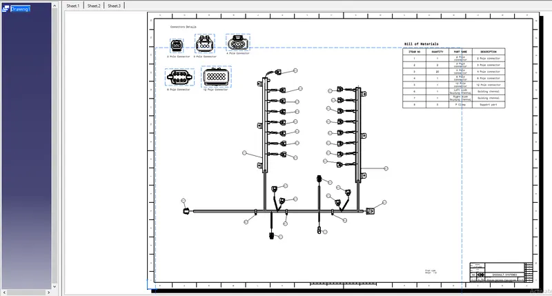
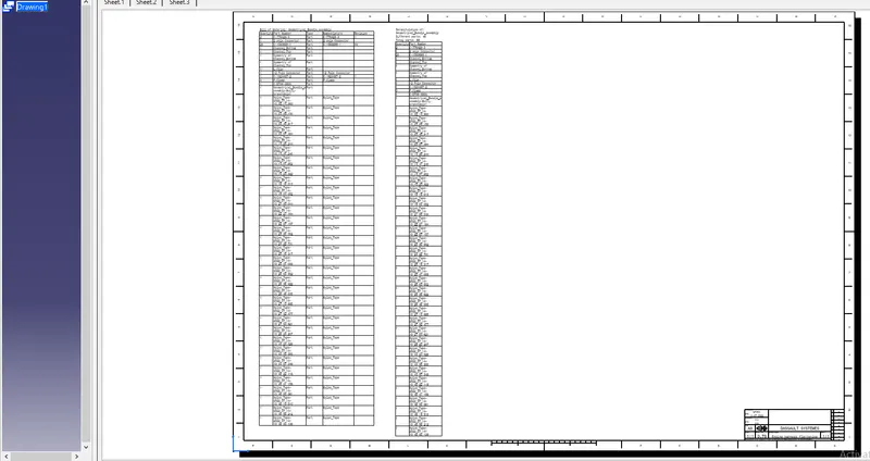
The final step is to create the drawing sheet, that's why go to the new drawing and select the front view option and select the flattened harness bundle inside the flattening file, and also import the bundle connection side view of each connector place it accordingly by using some command front view option. Then create the bill of material table and also import the 3D view of the geometric harness bundle of the engine harness assembly file by using the import 3D view option inside the drawing workbench.