Wiring harness design in CATIA V5 - 3D modeling Week 5 & 6 Challenge
ROUTING AND CONNECTING THE HARNESS A AND HARNESS B.
Objective: Define all the input connectors electrically by using the electrical part workbenchand later create the catalog for storing of all the connectors, later Route the harness A and harness B separately in individual product file and connect them electrically by using the electrical assembly workbench, also check the bundle connectivity of the each harness.
Input :
- The cad files of all the connectors required in the respective harness is provided.
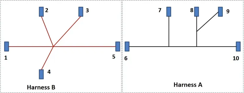
- The drawing for positioning of all the connectors in respective harness is provided.
Steps followed:
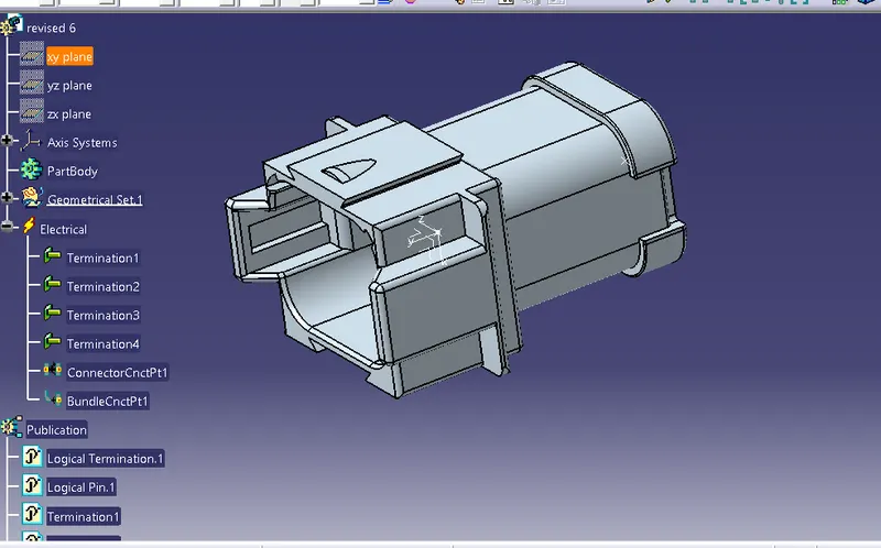
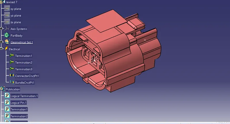
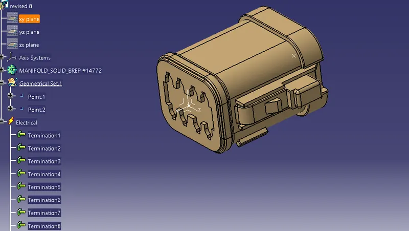
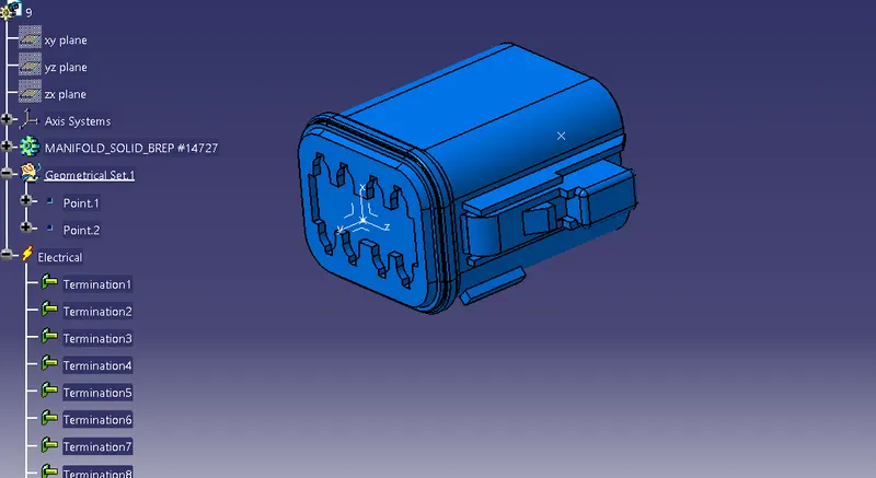
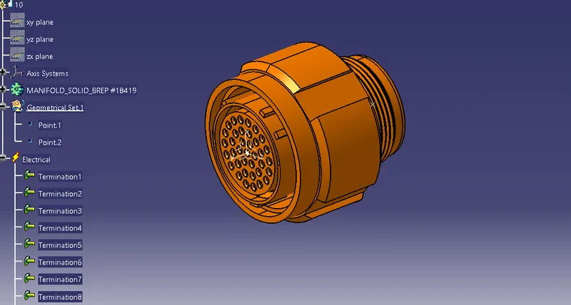
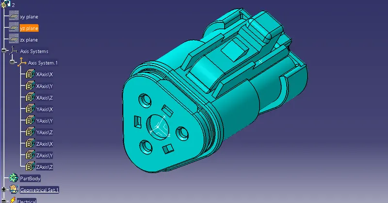
1)Download all the input files and store it in a single folder to manage your product in single file., the downloaded connectors must be electrically defined using the electrical part design workbench.
IMPORTANT NOTE: While defining the connectors make sure you list out all the terminals properly as later the terminals definition cannot be altered, once defined.
The connection control point and the bundle entry point is essential in all the connectors as it is pivotal at the time of routing.
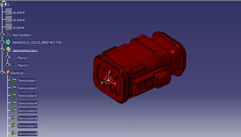
2)Create a main product and name it as a context assembly in which create two more product file by the name of HARNESS A AND HARNESS B these two will be our geometrical bundle assembly which can be defined from the electrical harness assembly workbench as geometrical bundle.
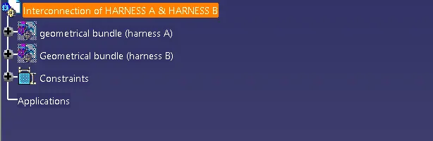
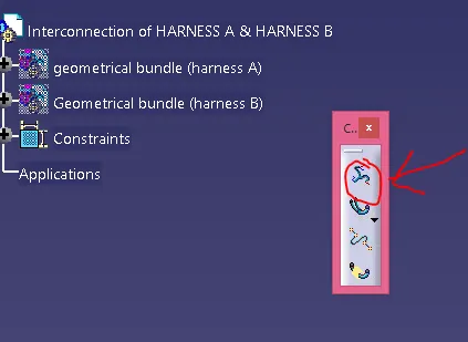
3)The geometrical assembly i.e HARNESS A & HARNESS B consist of all the conectors which are required in the respective harnesses, make sure you add those electrically defined connectors into the HARNESS A and HARNESS B assembies.
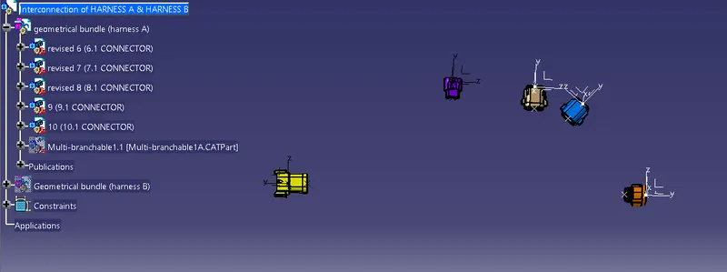
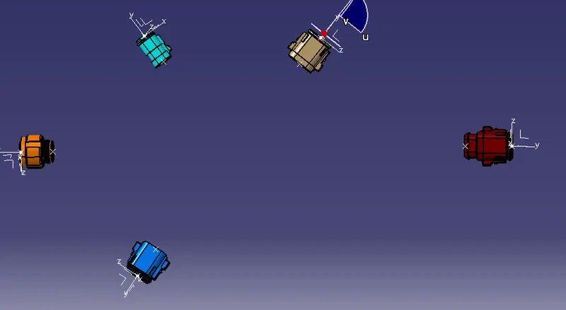
4)Open the HARNESS A and use the manipulation tool as well as the compass to adjust the position of the connector according to the drawing of the HARNESS A , you can use snap and rotational tool as well for positioning of the connectors.
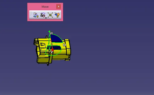
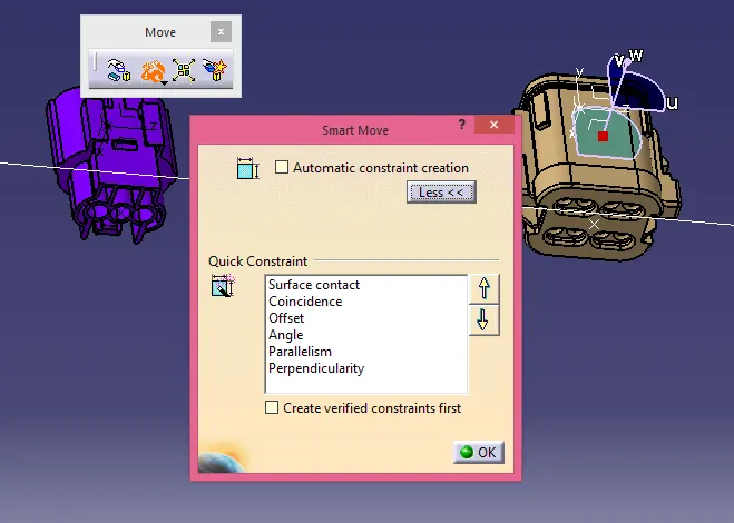
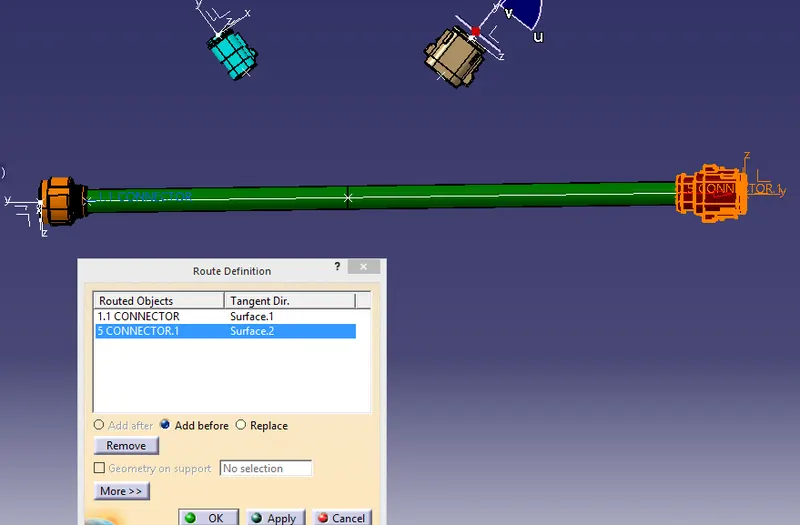
5)After positioning of the connectors in the respective positions routing can be done, following the electrical harness assembly workbench command called MULTI-BRANCHABLE , where you can define the branch defination.The path is selected between the selected connectors, we can alter the path of routing by changing or defining the path by various possible outcomes of tools like tangency, exterior path,automation with clearance etc.
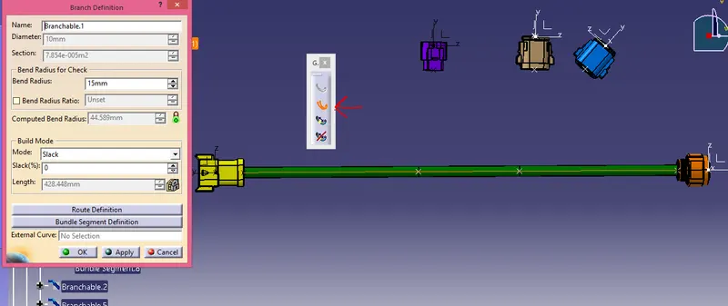
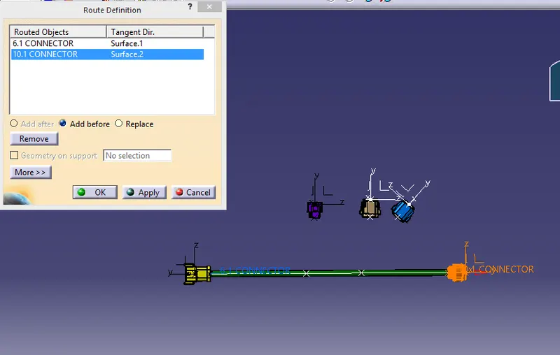
There will be one main branch and by creating the branch point we can create the sub-branches as well and repeat the same procedure for routing the components.
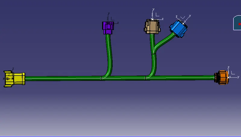
Similarly repeat the same procedure for creating the routing for the geometrical bundle assembly for harness B .
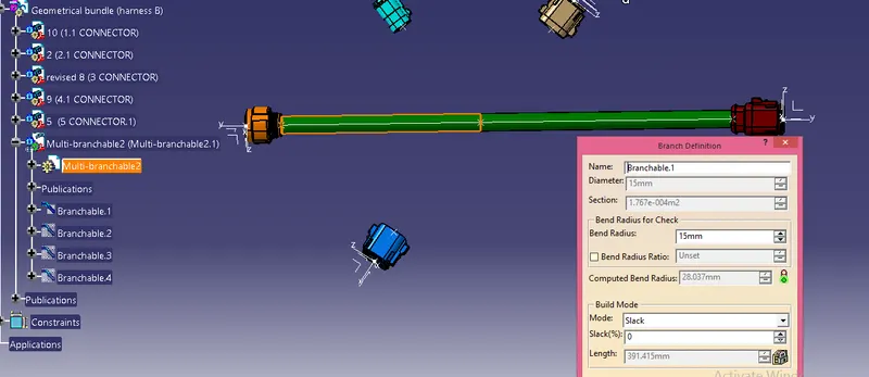 YOU CN
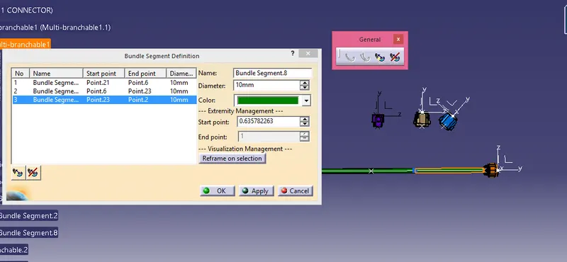
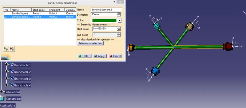
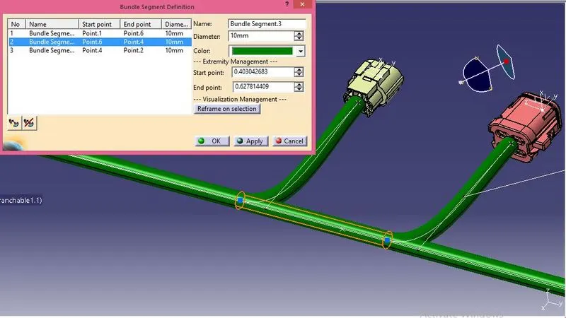
You can change the relative position for the branch point by using the bundle segment deginition command and chnage the lenth of starting point.
6)Sometimes it may happen that the branch you create for routing has some issues which will ultimately highlight the branch in red colour, this may happen due to various reasons and you need to find the best suitable way tackle or render that problem:The length of branch too small, branching point location issue ,connectors are not placed precisely and branch is not able to trace its path etc, here we had a issue related to branch point as you can see in the below attached images.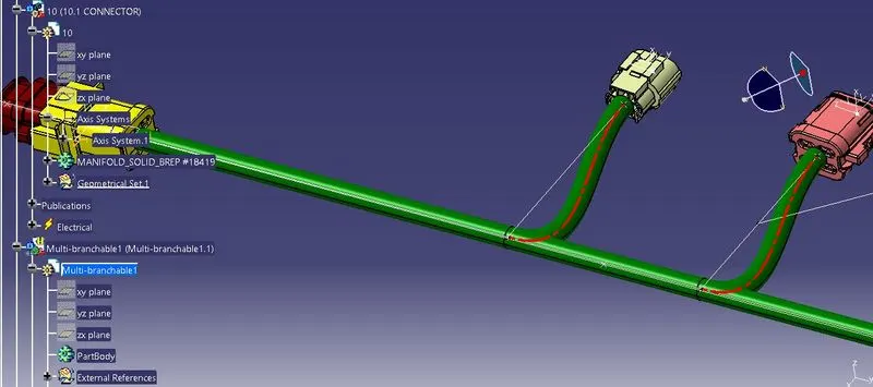
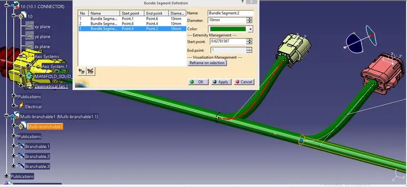
We changed the location of the branch point to analyze the problem, this can be done in bundle segment definition.
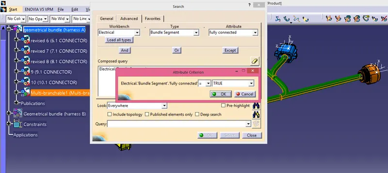
7)Next we need to check the bundle connectivity which can be done from edit-search-advance section where we can check the bundle connectivity of both the harnesses. We need to select the mukti-branchable from the tree structure in order to get the desired results.We can get either false results for the one who are not connected or true result for the connected branches.
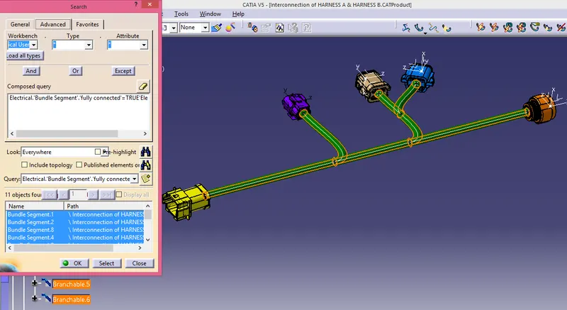
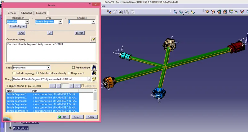
8)Now switch to the main context assembly then we need to connect the harness A and Harness B this can be done either by using the manipulations and compass but as you have defined the connectors electrically so it would be better enough to jump into electrical assembly design where you can connect parts electrically defined and they will orient according to the configration of the axis system defined while setting up the connectors electrically.
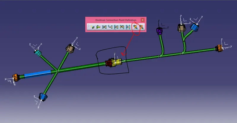
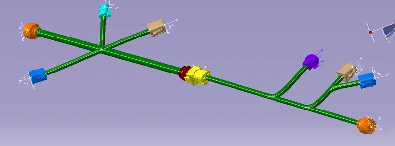 terconnecting the Harness A and Harness B now be can
9)Now we can add the annotations for our reference as well as it would be easy for the manufacturing team to have clear interpretation of the details of the assembly. 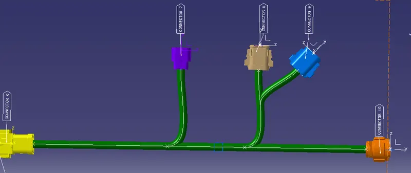
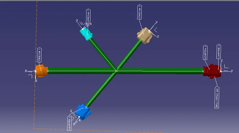
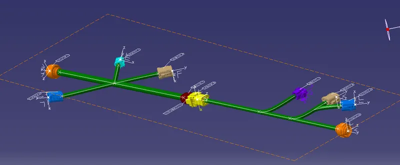
10)Add the protective covering from the catalog if required as it is not mentioned but it will ultimately improve the asthetics.
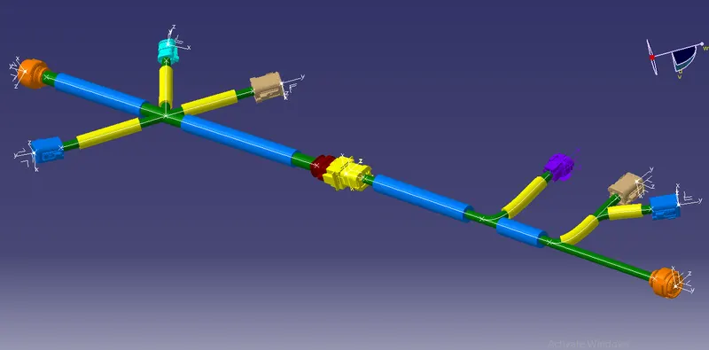
11)Create the CAT part of the the whole product file by tools-create cat part in assembly workbench.
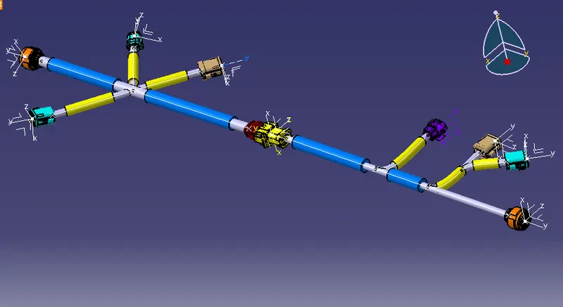
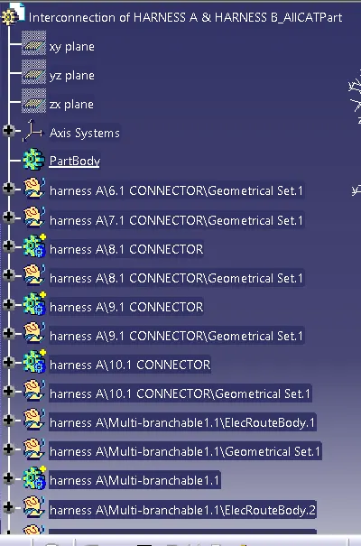
detail tree structure of cat part as we have selected detailed part bodies while converting the product to catpart.