Wiring harness design in CATIA V5 - 3D modeling Week 4 Challenge
Wiring harness design in CATIA V5 - 3D modeling Week 4 Challenge
AIM :
To upload the connectors then define it as electrical part, perform routing operation and then apply a protective covering on it.
PROCEDURE:
Given are the connectors for routing purpose:
- DT06-4S
- DT06-6S
- DT06-2S
- DT06-08SA
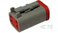
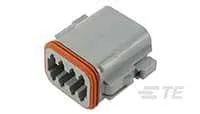
DT06-4S:
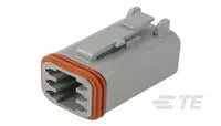
DT06-6S:
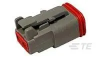
DT06-2S:
DT06-08SA:
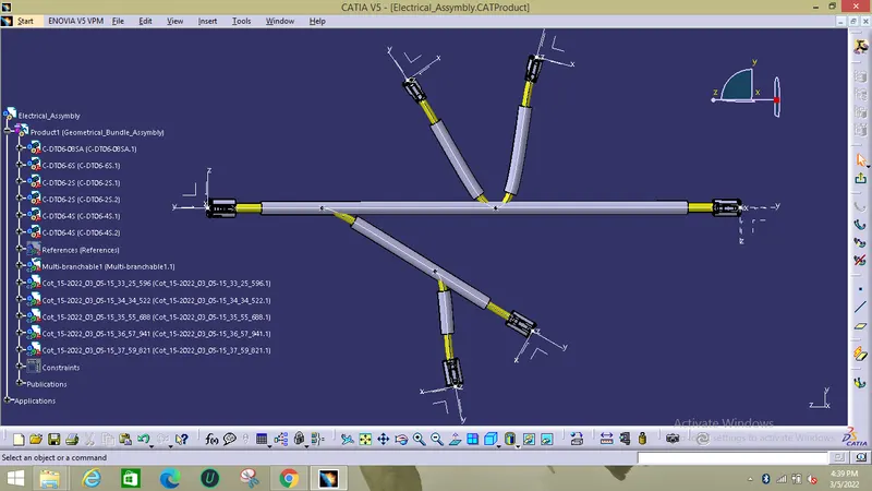
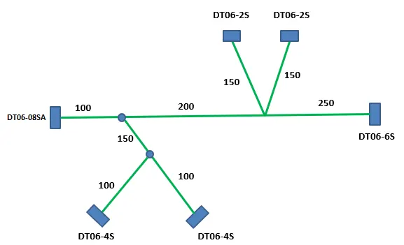
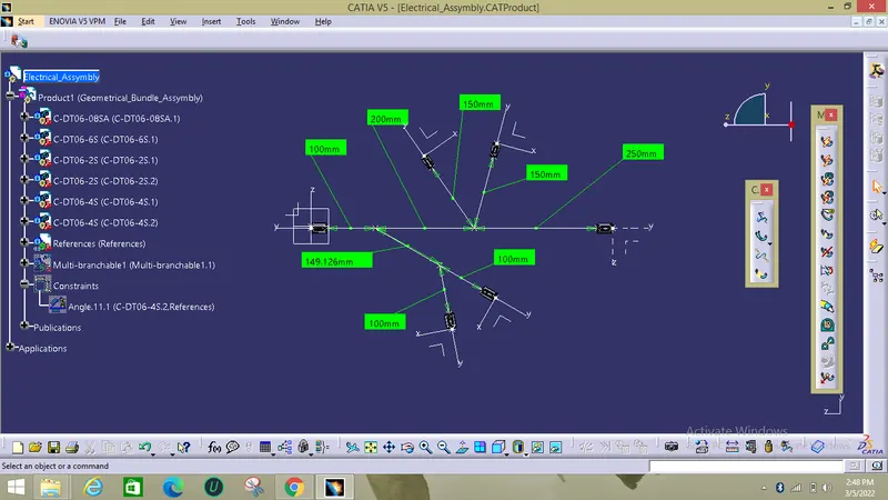
The required routing system which should be prepared is:
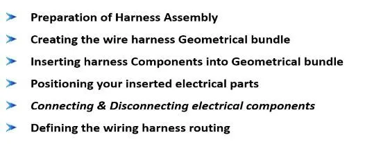
STEPS TO BE FOLLOWED FOR ROUTING:
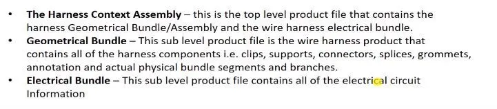
- When creating the wire harness bundle segments you are first required to insert the electrical components that you need to route the wire harness from and to I.e. before you can route the wire harness you will need an electrically defined components to route the harness from, an electrical harness connector to route the harness to and also some electrically defined harness clips in between to fix your harness route.
- As well as this data you will require the surrounding part data of the area you are routing your harness from other departments. I.e. Body data, trim data etc basically any other data within the area of your harness route.
- Other departmental cad data should be referenced into your context top level assembly and NOT your actual harness geometrical bundle assembly.
- This data should also be removed from your context assembly before saving.
- Ensure that all harness components that are needed in Assembly are Electrically defined with all required parameters before adding them in assembly. This is pre-requisite.
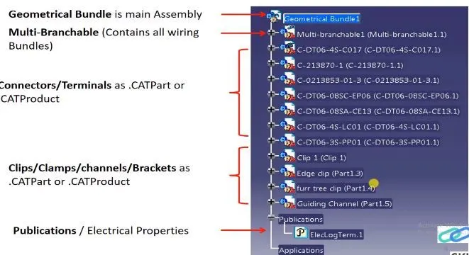
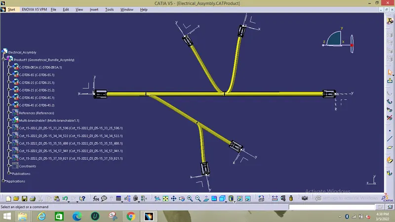
The final tree is shown below:
The given requirement for routing is pre determined in a single plane using points and lines with the given bundle distance.
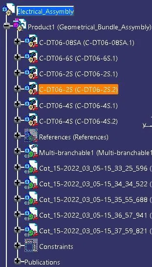
Now after defining all parts as a electrical definition and a product assembly is created and all the parts were added into the Assembly in the name of geometric bundle.
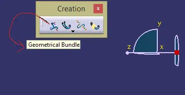
Now using Geometrical bundle command in the electrical wiring harness assembly all the mechanical parts were converted into electrical bundle.
After converting the mechanical parts into electrical bundle Mutltibranchable command is selected to crate the branches in between the connectors.
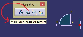
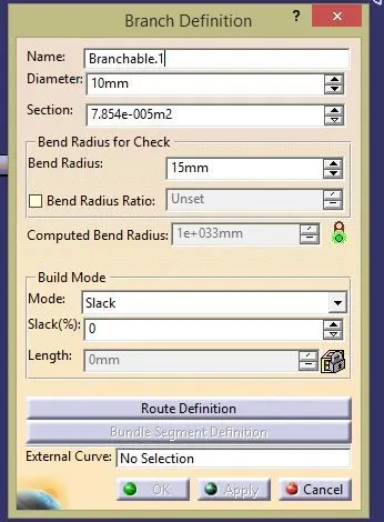
Now for creating the new branch Branch definition command is used where the routing definition, bend radius is given as input.
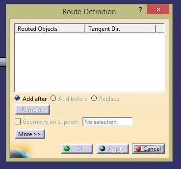
After creating the branches branching point were added in between the branch to provide the mutliple branches.
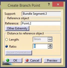
The created branches and sub branches were shown in the below image:
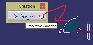
Now Protective covering were added for the branches for protection and asthetic purposes:
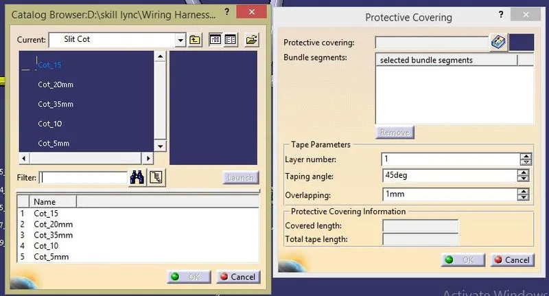
- The Protective covering dia should be greater than the dia of the branch.
- If the dia of branch is 10mm protection inner dia should be 1.5 times the branch cable.
- According to that the protective coverings dia were choosed from the previous catalogues which are saved.
The Protective Routing and the final image is shown in the below image: