Wiring harness design in CATIA V5 - 3D modeling Week 4 Challenge
AIM
To Route the following harness layout in Electrical workbench. Make assumption for harness bundle diameters. Use Following connectors as shown in layout diagram and Add protective covering on all branches connected to DT06-2S & DT06-4S connectors. Keep end extremity at 30mm (from connectors end)
WIRING HARNESS ASSEMBLY
- Preparation of Harness Assembly
- Creating the wiring harness geometrical bundle
- Inserting harness component into geometrical bundle
- Positioning your inserted electrical parts
- Connecting and Disconnecting electrical components
- Defining the wiring harness routing.
WORKING PROCEDURE
- Create Product name it as Wiring harness assembly
- Create new product name it as geometrical bundle
- Open Mechanical Assembly design workbench
- Download connectors
- Create Electrical design with Bundle connection point and connectoe connection point
- Copy And Paste the respective connectors in Geometrical bundle product
- Use Manipulation command and move to respective place
- After that click Geometrical bundle workbench .it changes electrical part
- Open Wiring harness assembly
- click multiple branch document
- create routing diameter 10mm from connector DT06-08SA TO DT06-06SA
- After that ADD BRANCH Point in required area for branches
- Again click Multible branch document
- create a sub branches in DT06-4SA AND DT06-2SA Connectors
- Click Protective covering and select the catalogue for cot tubes 15mm
- Start extrimity point and end extrimity point 30mm for DT06-08SA and DT06-06SA connectors
- Click Protective covering and select the catalogue for cot tubes 10mm
- Start extrimity point and end extrimity point 30mm for DT06-2SA and DT06-4SA connectors
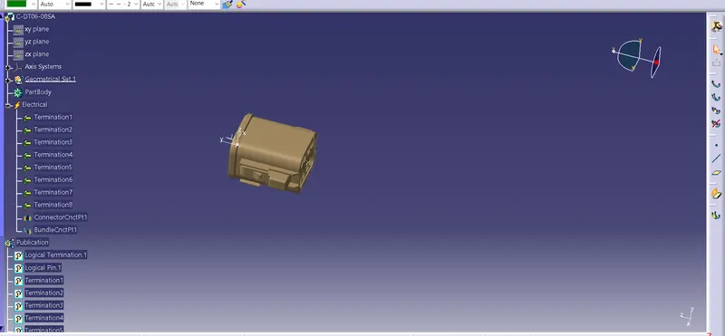
DTO6-08SA CONNECTOR
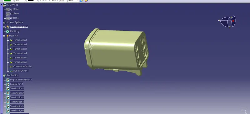
DTO6-06SA CONNECTOR
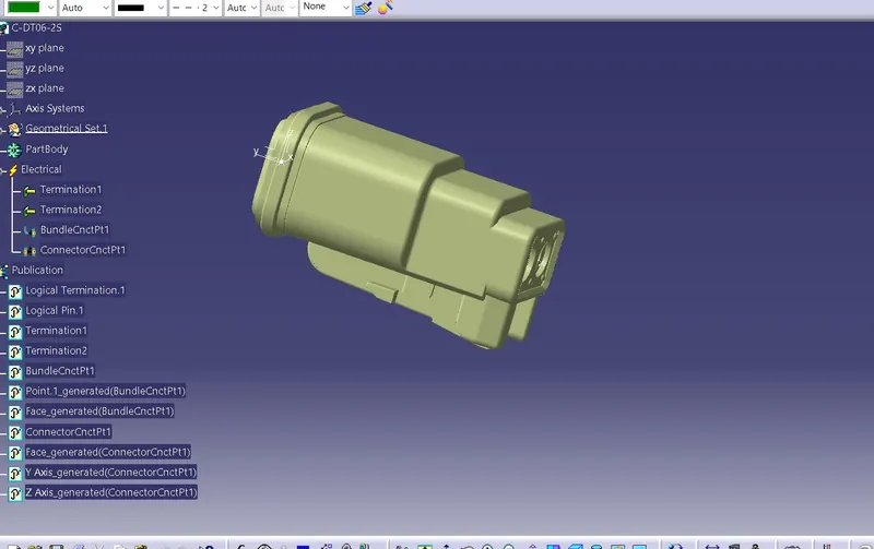
DTO6-2SA CONNECTOR
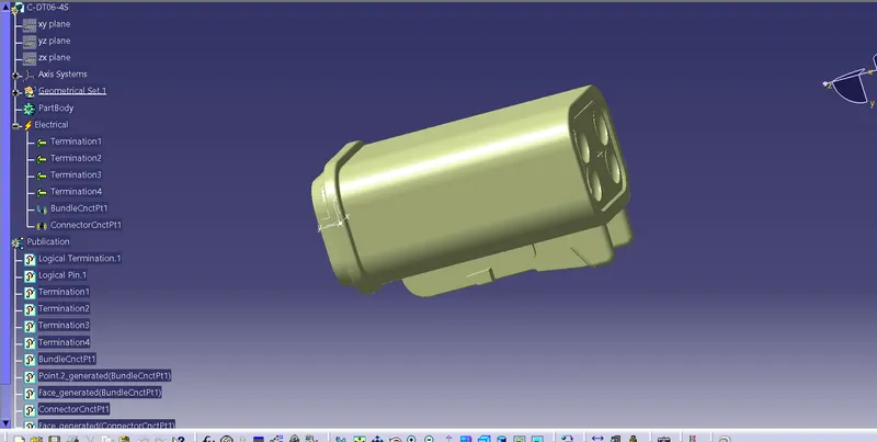
DTO6-4SA CONNECTOR
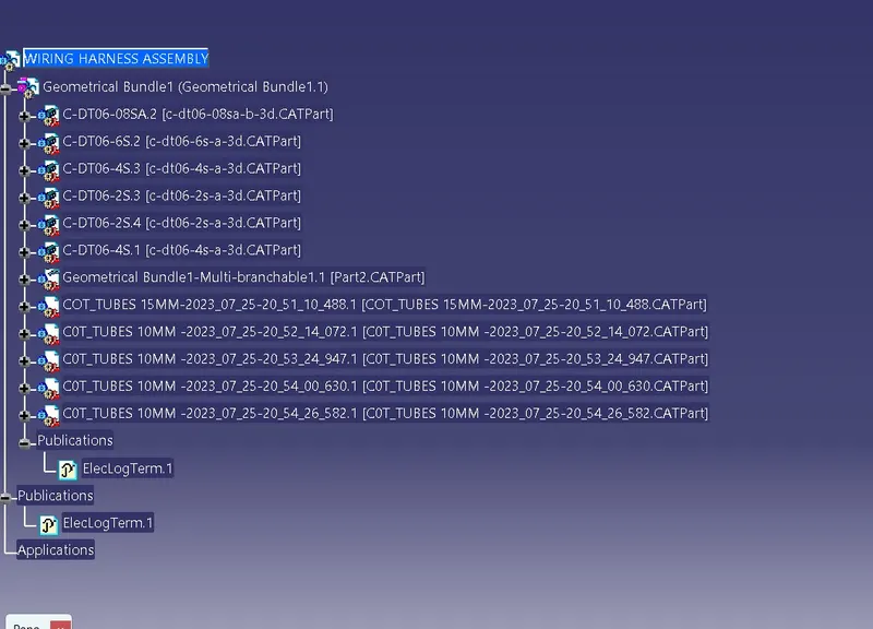
TREE STRUCTURE
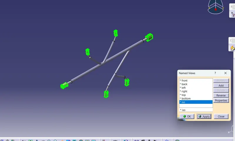
ISOMETRIC VIEW
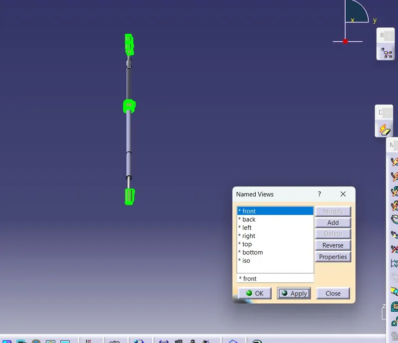
FRONT VIEW
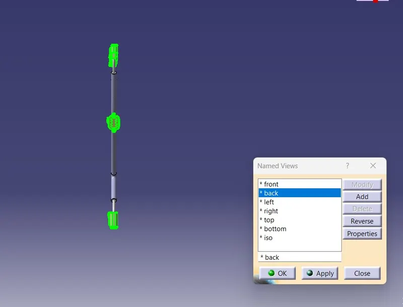
BACK VIEW
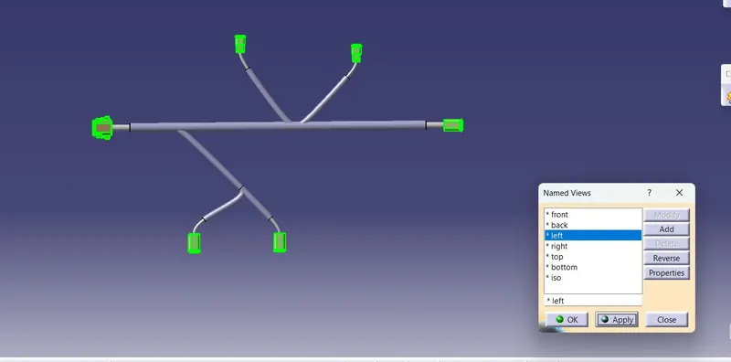
LEFT VIEW
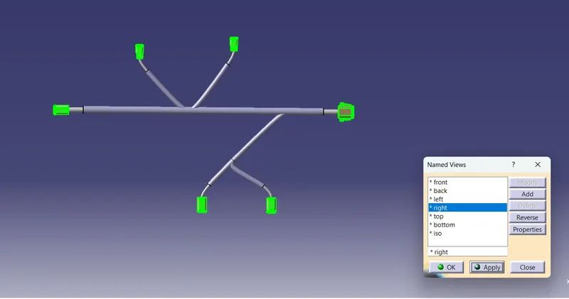
RIGHT VIEW
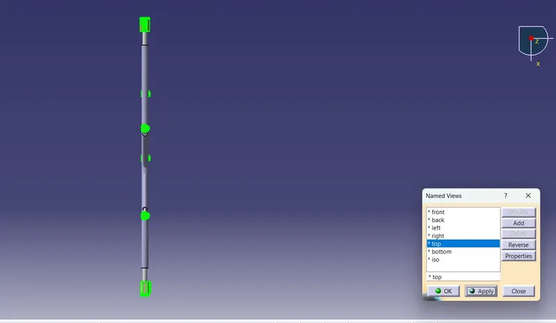
TOP VIEW
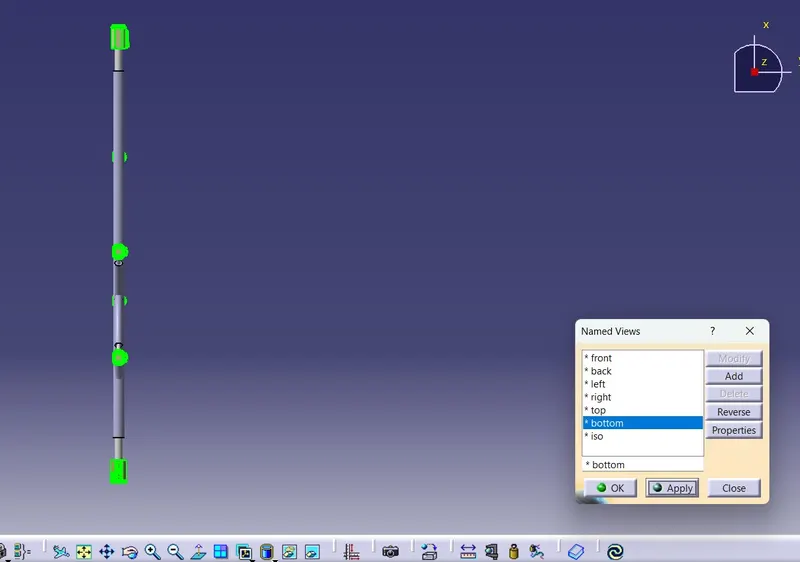
BOTTOM VIEW
RESULT
Thus, the following harness layout in Electrical workbench. Make assumption for harness bundle diameters. Use Following connectors as shown in layout diagram and Add protective covering on all branches connected to DT06-2S & DT06-4S connectors. Keep end extremity at 30mm (from connectors end) to be created