Wiring harness design in CATIA V5 - 3D modeling Week 4 Challenge
step 1:
Downloading the required connectors for the wiring harness assembly.
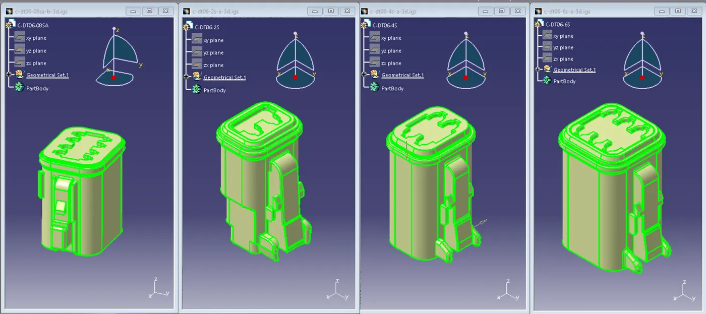
step 2:
Adding the geometrical properties which are necessary such as points & axis System to the components accordingly
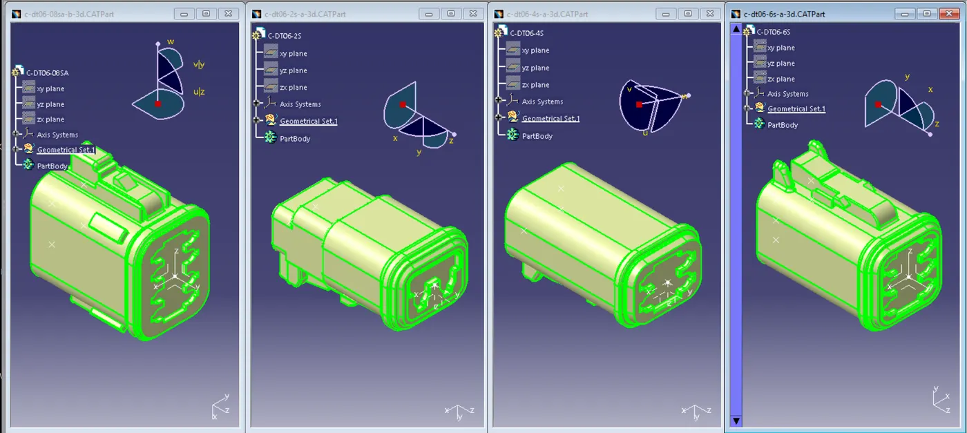
step 3:
Go to >> Electrical part design workbench to define the part as connector using connector definition command also select the number of terminations required
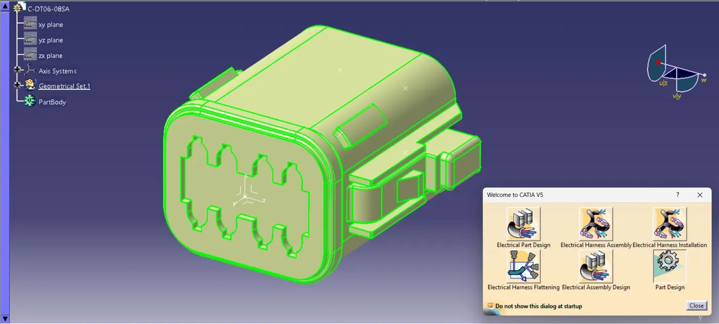
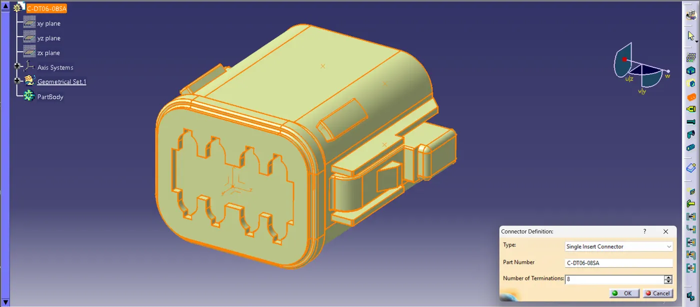
step 4:
Now our mechanical part is converted into electrical component let's add some other electrical properties to it such as connector connection point & bundle connection points for electrical connections
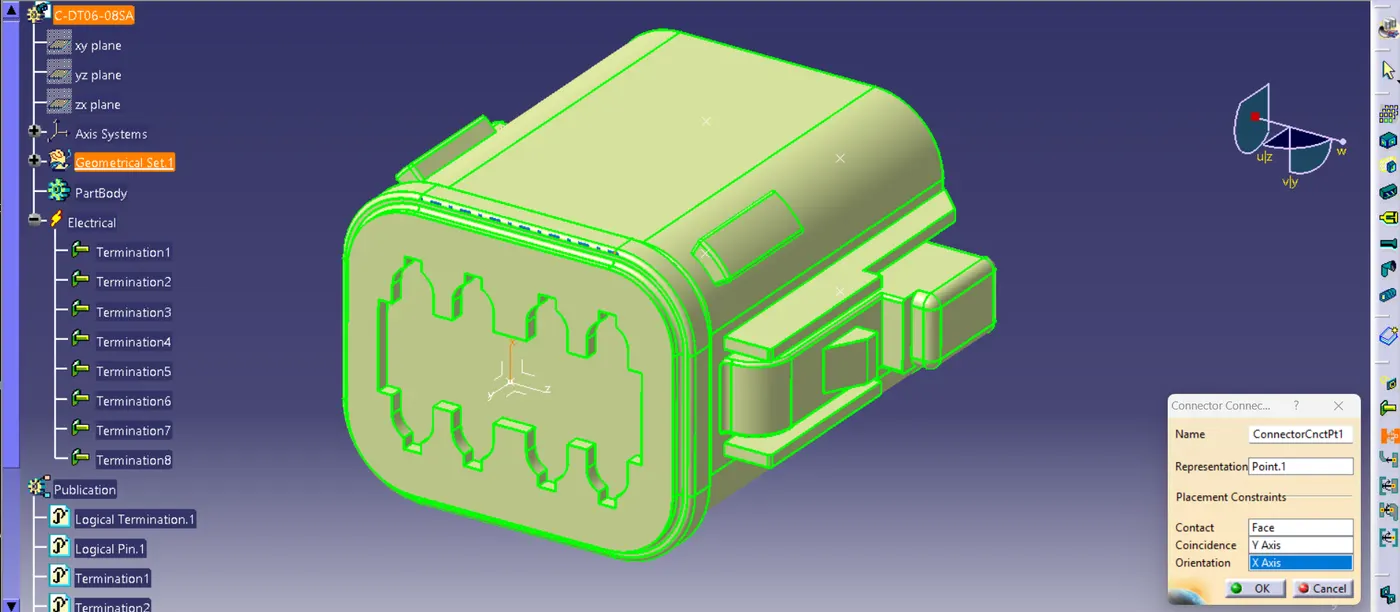
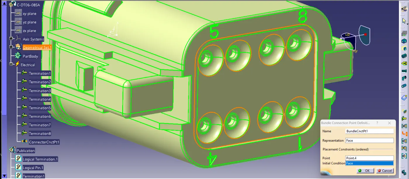
you can see all the necessary electrical properties have been to the conductor & it is electrically fully defined.
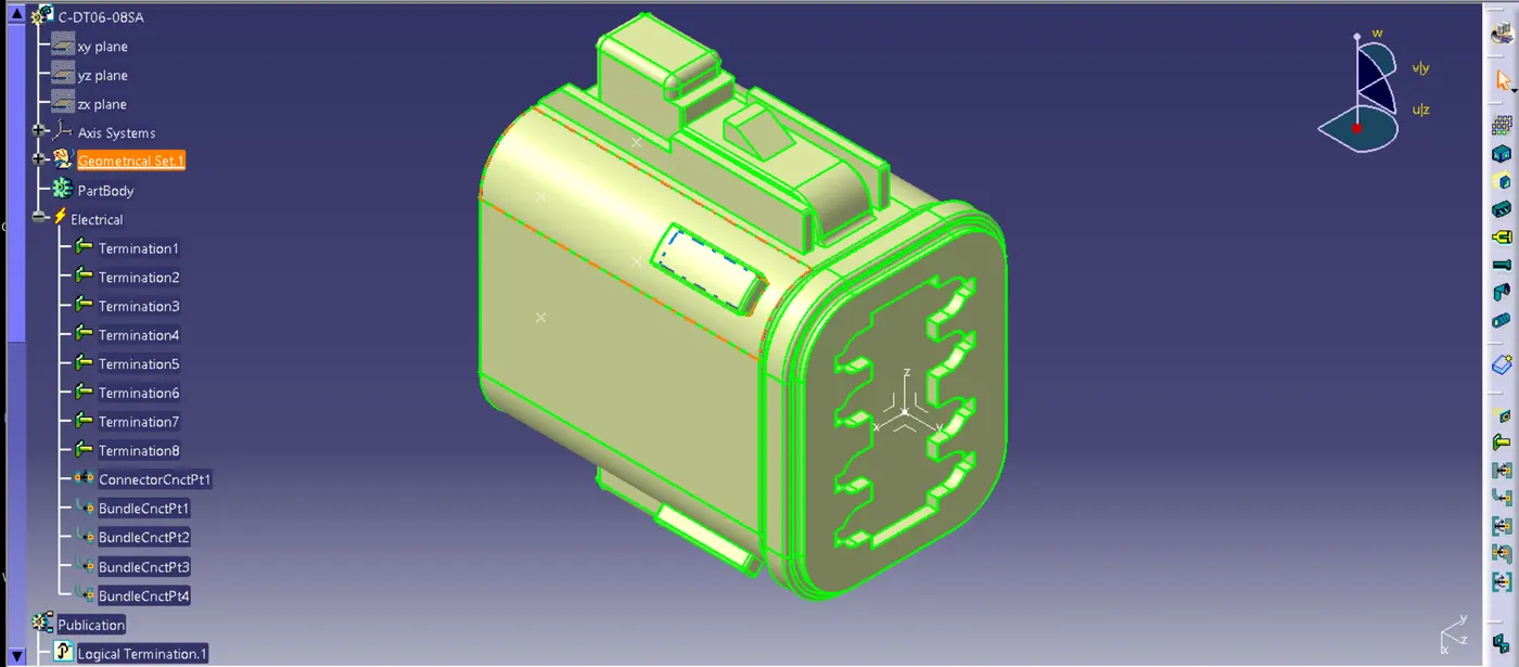
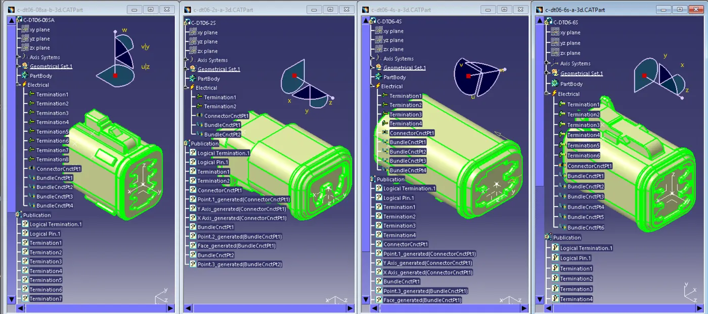
Similarly adding the properties to the other connectors on by one accordingly
step 5:
In the next step we are going to create a catalog file and add all the components to it under connector family
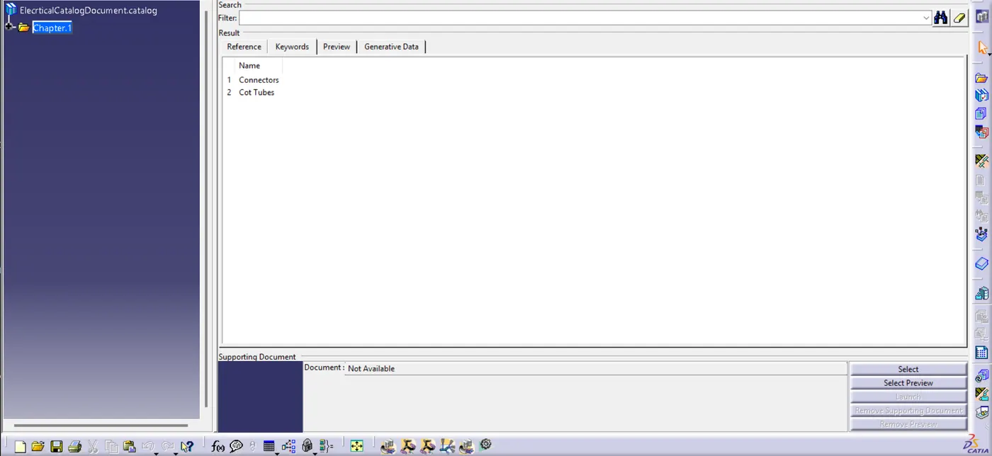
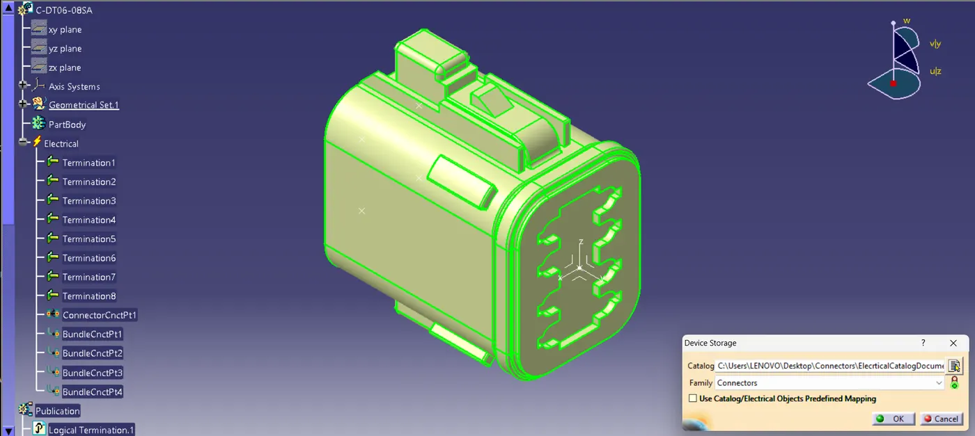
step 6:
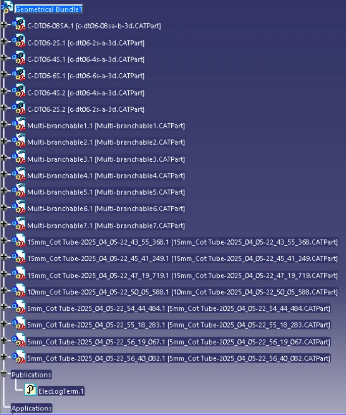
Let's create some protection coverings which are needed for the wiring harness assembly (15mm, 10mm & 5mm) and add them to catalog under cot tube family
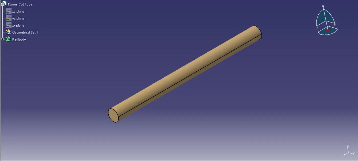
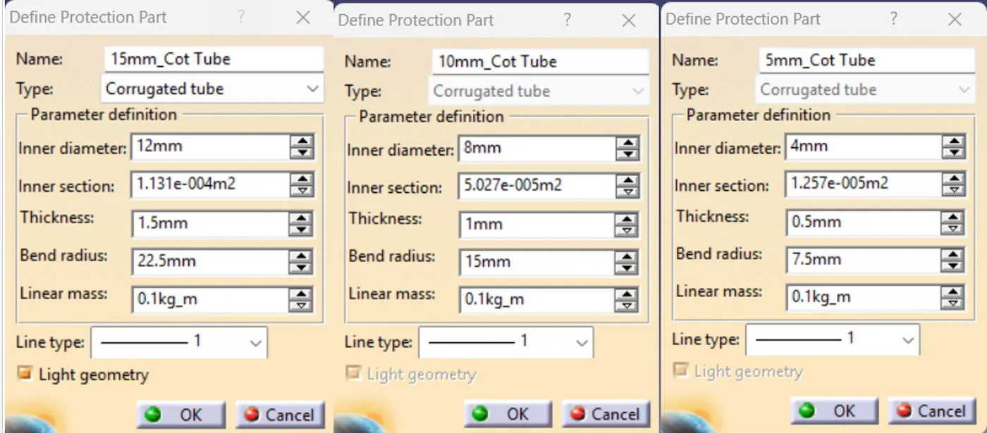
step 7:
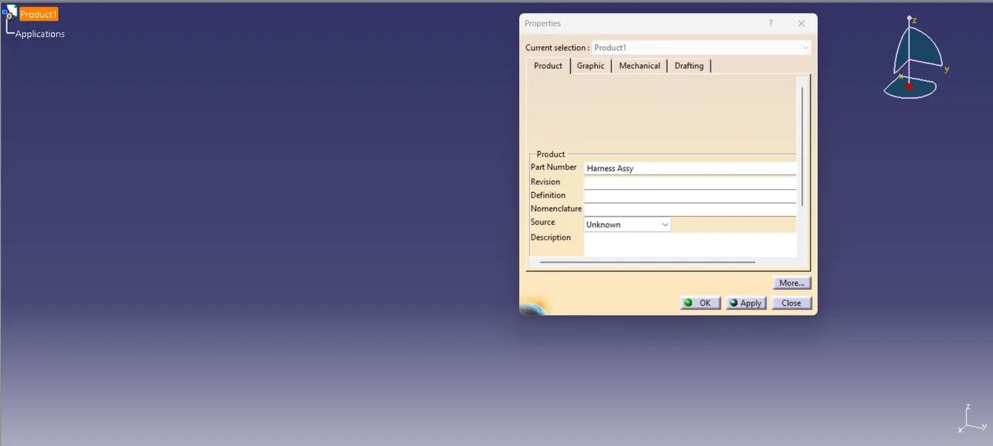
Then create a product file and rename it as 'Electrical Harness Assembly'
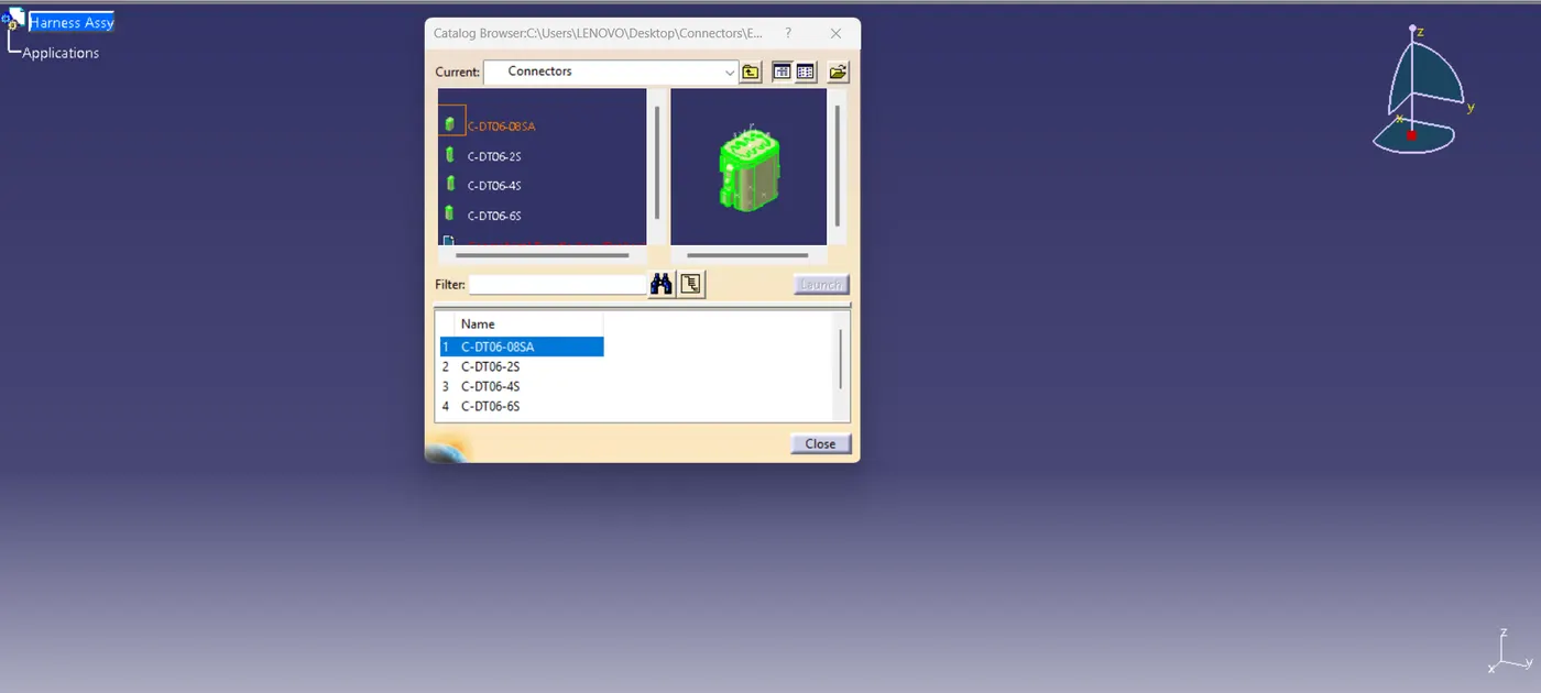
now it's time to add all the connector from the catalog we saved previously to the product file using browse catalog command
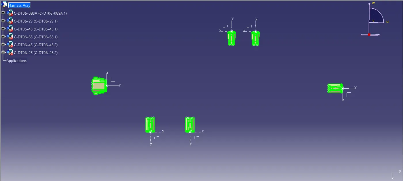
step 8:
Place the component at required distances to make multiple branches using different tools available in the assembly workbench
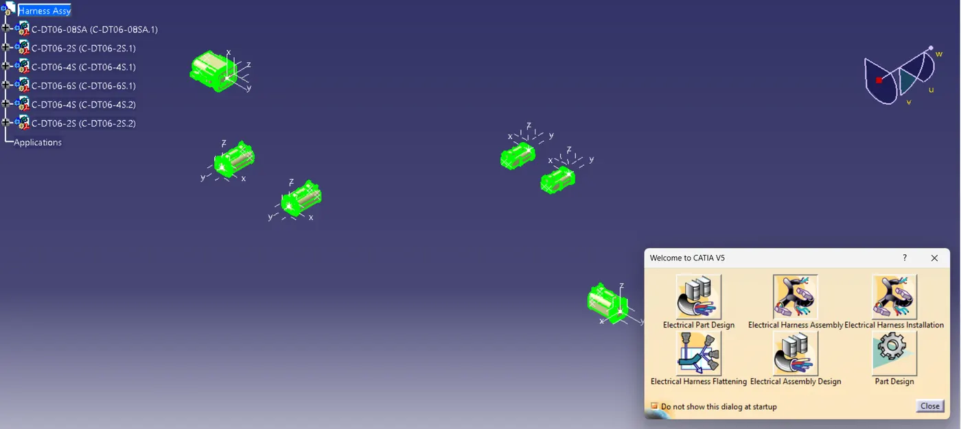
Let's come to Electrical wiring harness workbench 7 define the assembly as an electrical assembly using multi blanchable command
step 9:
Now we need to add multiple branches and branch points to prepare the wiring harness
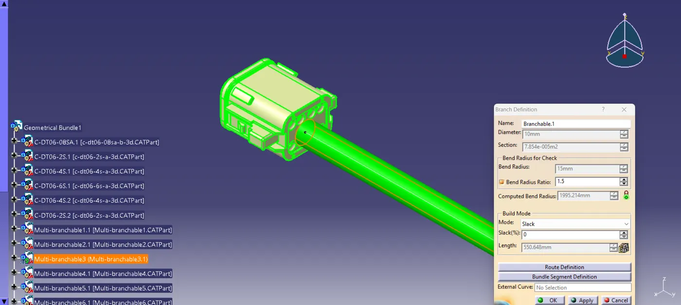
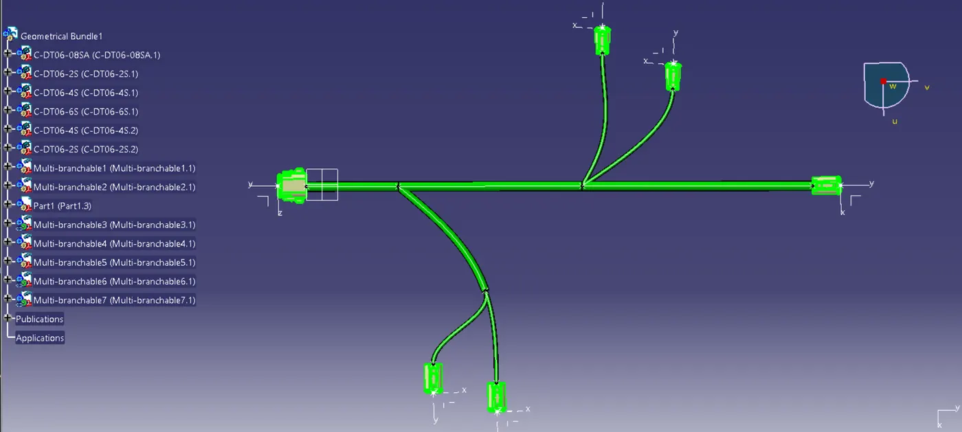
step 10:
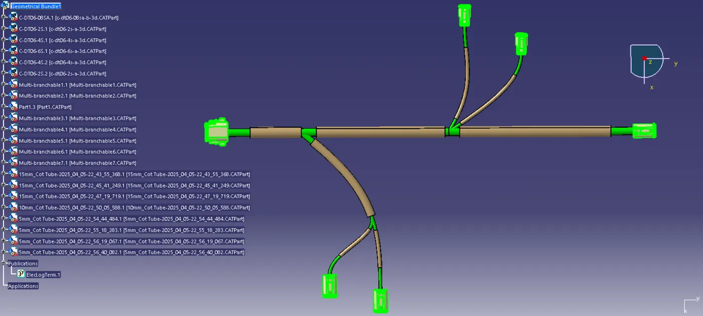
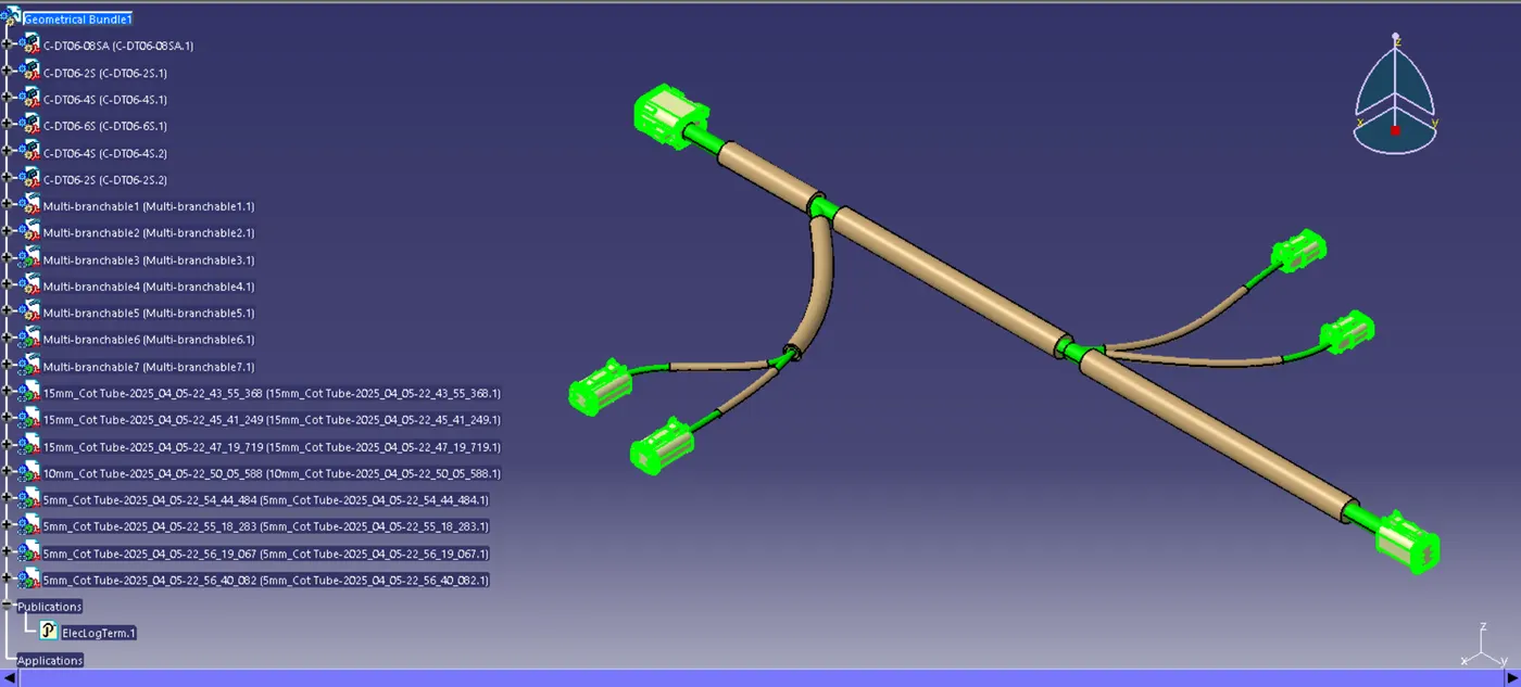
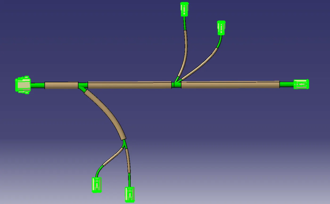
In the next step we are going to add protection covering from the catalog to the wiring harness we created according to the bundle diameter
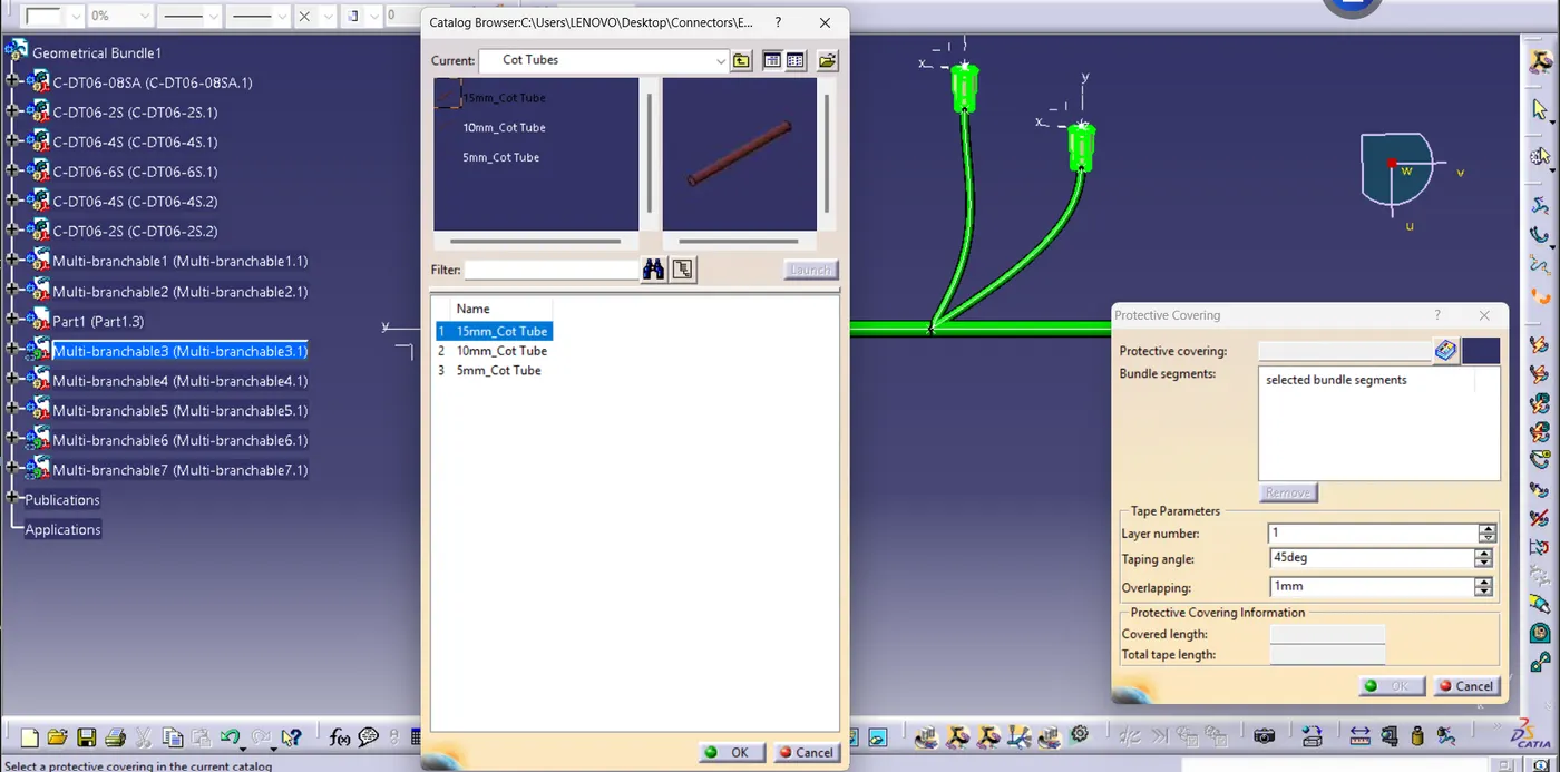
maintaining the 30mm distance from the connector end
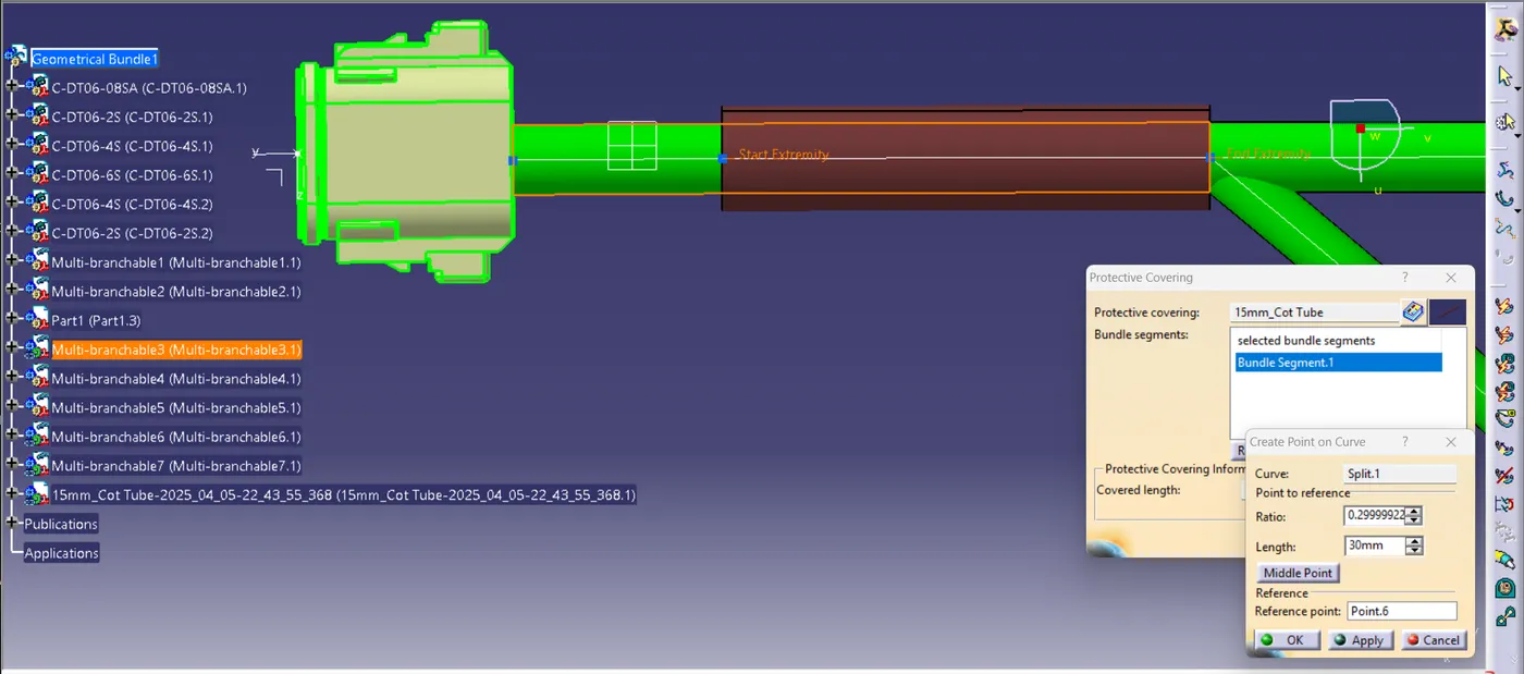
Finally our wiring harness assembly is complet now