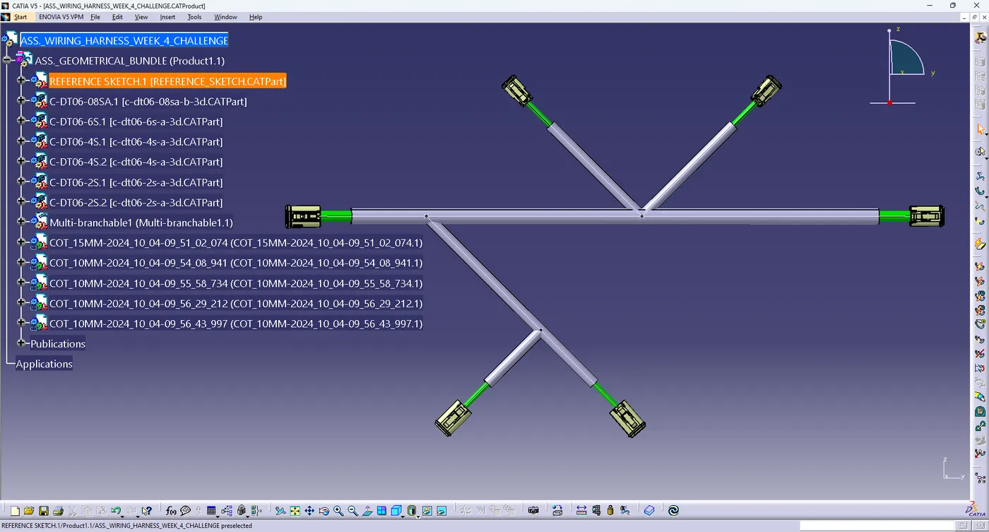
Wiring harness design in CATIA V5 - 3D modeling Week 4 Challenge
3D modeling Week 4 Challenge
:- wiring harness is an assembly of many components in it,it follows the assembly structure in virtual environment too.
- Geometrical Bundle is main assembly
- Multi branchable (contains all wiring Bundles)
- Connectors/Terminals as .CATPart
- clips/clamps/ channels/brackets as .CATPart
- Publications/Electrical properties
> CREATING THE WIRE HARNESS GEOMETRICAL BUNDLE
- create New Product File
- Enter Desire details like Description part number then click ok
according to given data download all connectors in step file then change into part file
- in
this some commands use like define mounting equipment, define
connectors, define connector connection points , define bundle connection
points, define cavity connection point,
1. according to given data create a sketch create points because connector located to desired position to fast so create a sketch given name of the sketch to reference sketch
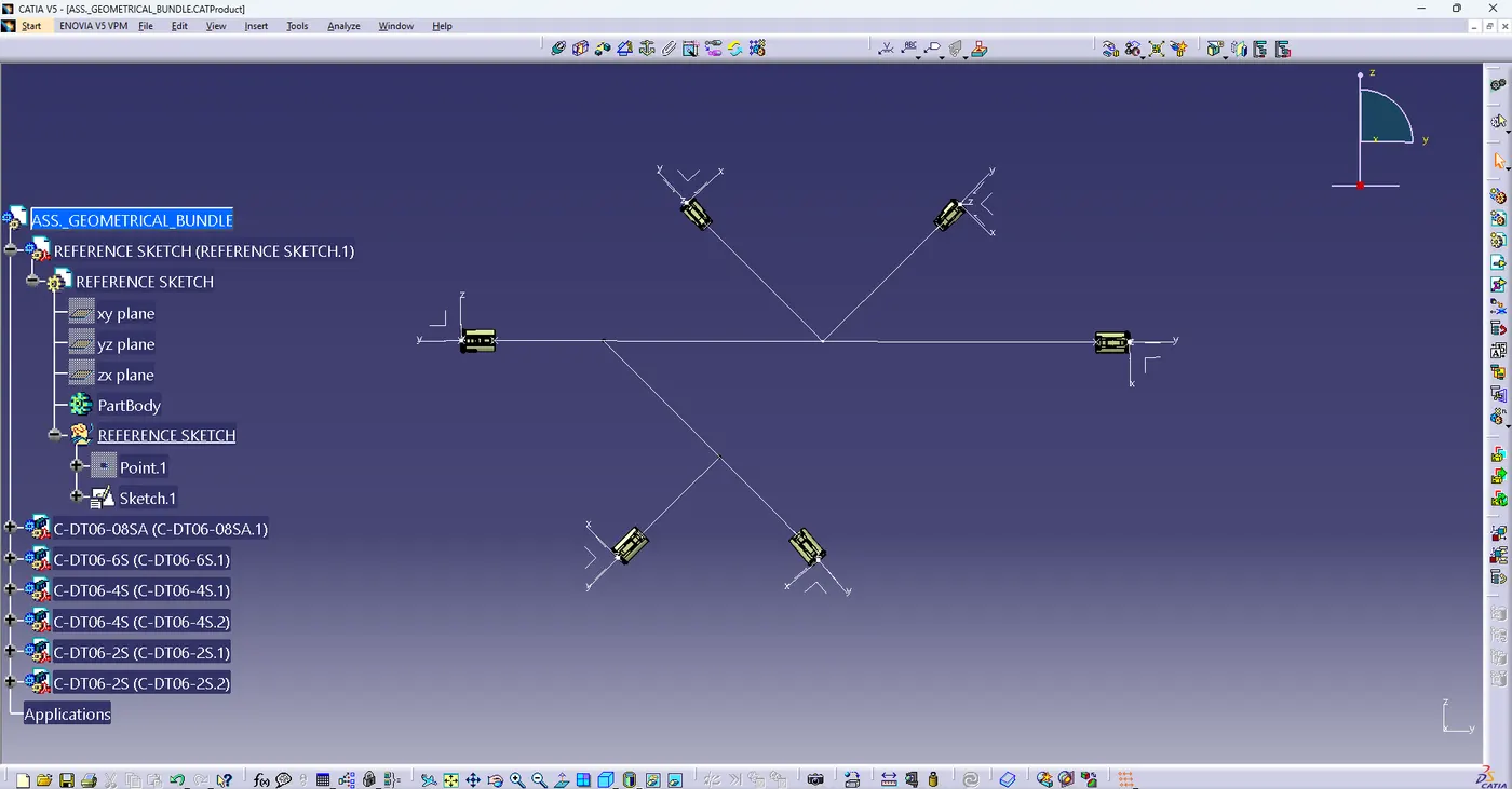
2. open ass. geometrical bundle> select existing component command > insert reference sketch
3. insert all connector by existing components command
4.all connectors located by manipulator ,snap command
5. ass.geometrical bundle product file switch to electrical wiring harness assembly workbnch > double click on ass. geometrical bundle > go to the electrical bundle command icon select it .
6. select multi branchable document command > open branch definition > insert diameter of branch
7. select Route definition> select connectors to join branches
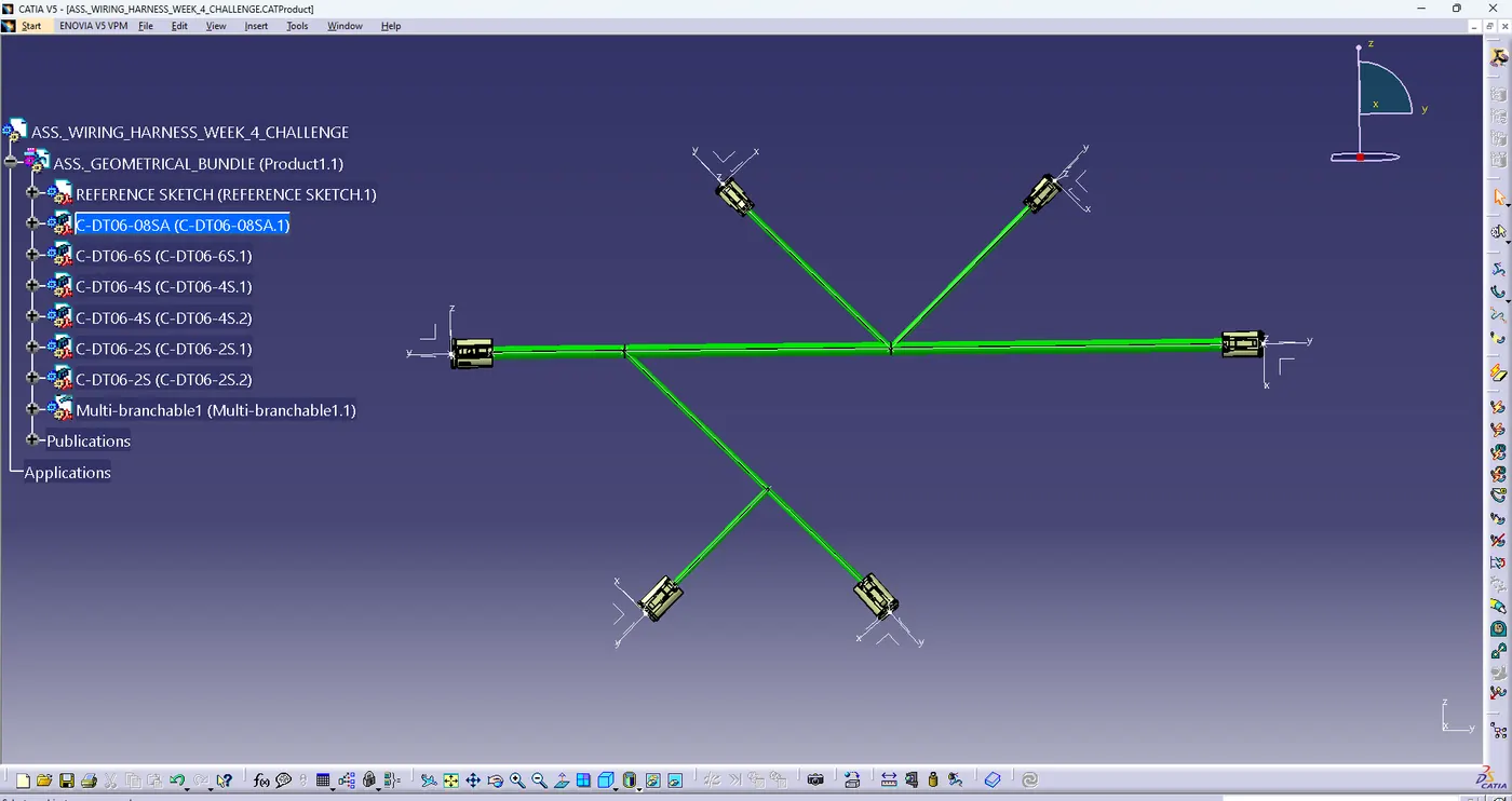
8. select add branch point command then select branch point according to given data then create branch
9. select protective covering command to cover all branches > select catalog option for select cot tube which you select .
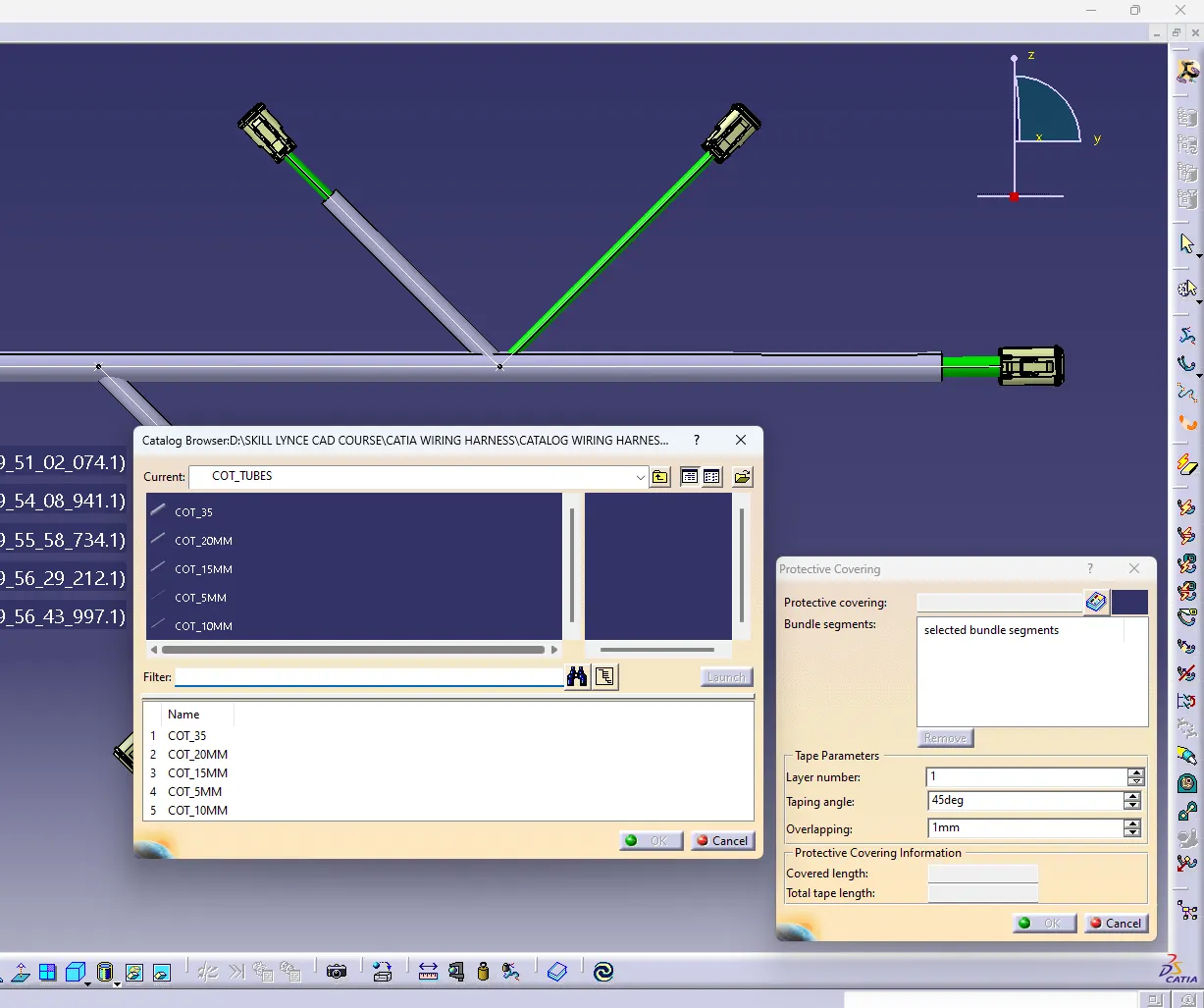
10. according given data keep end extremity of 30mm end of the connector .
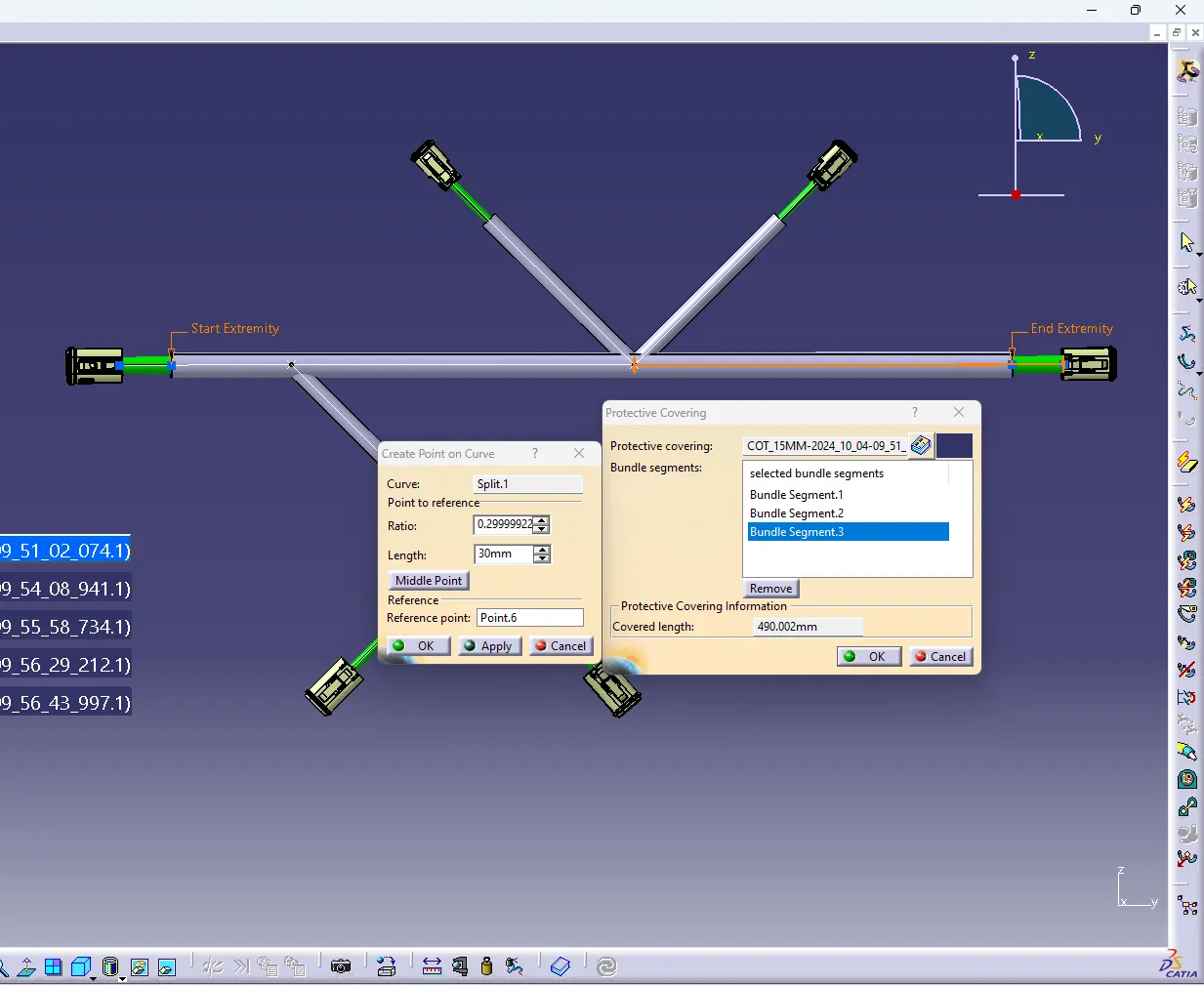
final look for assembly