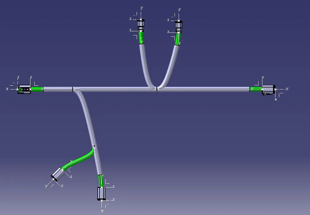
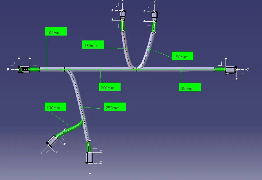
Wiring harness design in CATIA V5 - 3D modeling Week 4 Challenge
Aim:
Route the following harness layout in Electrical workbench. Make assumption for harness bundle diameters. Use Following connectors as shown in layout diagram.
Add protective covering on all branches connected to DT06-2S & DT06-4S connectors. Keep end extremity at 30mm (from connectors end).
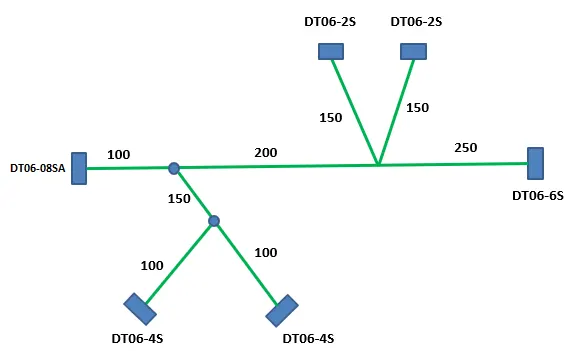
DEFINING ELECTRIC PARAMETER FLOW CHART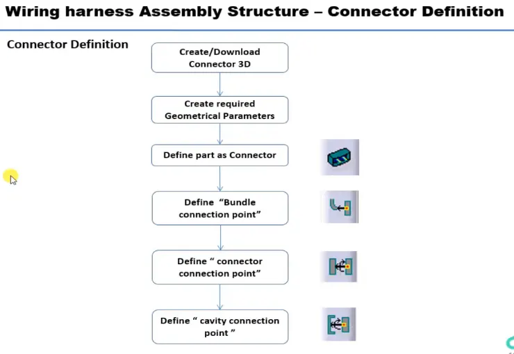
Following Parameters are required to defined for any connector:
Geometry Parameters - Points & Co-ordinate system (Axis)
Connector connection point - This point is used for the connection of one connector to another connector.
Harness bundle entry point - This point defines where the harness bundle segment point will end when routed to the electrical connector.
Cavity connection point (Optional) - This point is used to define the connection of a connector to a connector clip. This only applies to connectors which have the mounting feature for a connector clip.
CONNECTOR FEDINATIONS IN CATIA V5
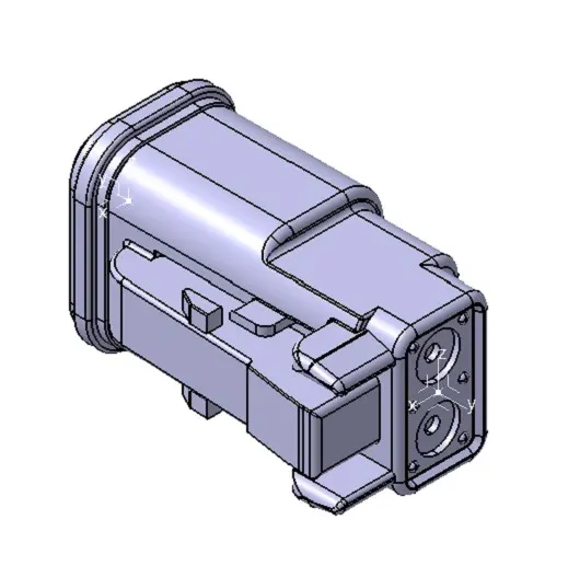
1. Create midpoint on the contact face which will be normal to wire bundle insertion.
2. Create Axis System with respect to the point which we have created and defining the axis direction as shown below.
3. Switch to 'Electric Part Design'
4. Define the part as connector in Catia, give no. of termination equal to entry points for wire.
5. Define Bundle connection point.
6. Define connector connection point.
So, likewise we need to define all the connector as electrically.
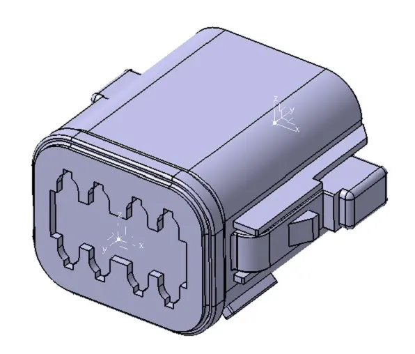
1. DT06 – 08SA
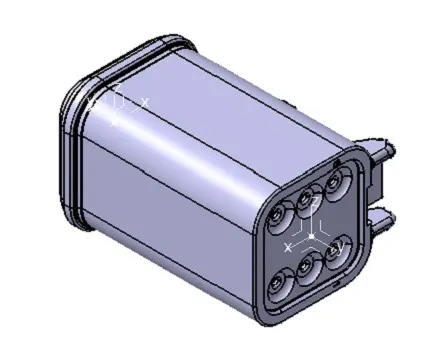
2. DT06-6S
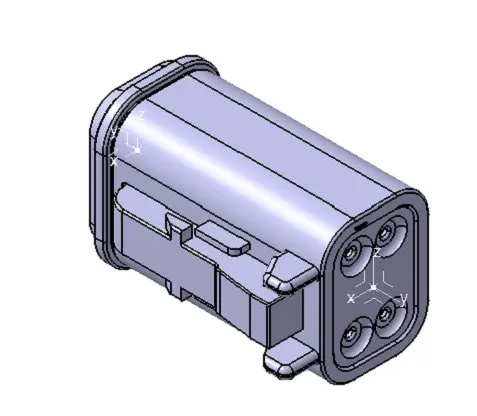
3. DT06-4S
4. DT06-2S
CREATING WIRING HARNESS ASSEMBLY STRUCTURE
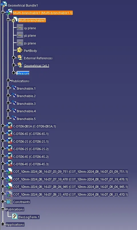
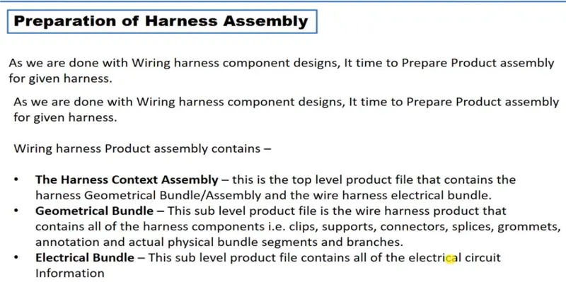
Now Create the Electric wire harness context assembly and Geometric bundle as a subassembly containing all the electric parameters as shown below,
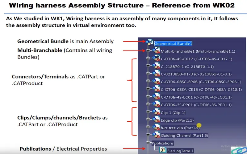
1. Add all the connectors which are electrically defined to the Geometric bundle assembly.
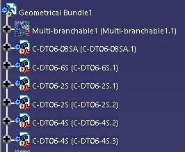
2. Then define this Geometric bundle assembly as electrically, for that we need to switch to Electric harness assembly workbench.
3. select Geometric Bundle then click on Geometric bundle assembly (In specification Tree)
4. Now, to position all the connector as given in input file,
5. Switch to Mechanical assembly workbench, Position the connectors by using Manipulation, snap, smart move and compass commands.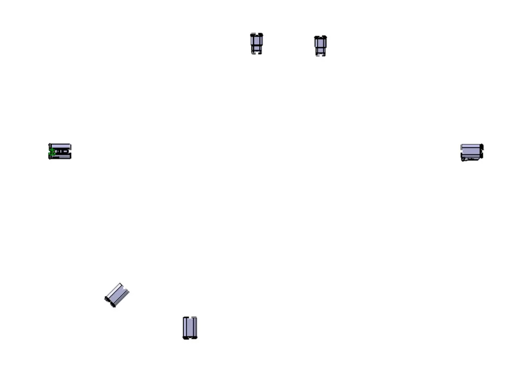
6. Now switch to Electric harness assembly workbench.
7. Using the Multi Branchble component Command to create the Bundles.
7. Now to route the harness, after selecting multi branchable documents workbench changed to wire harness installation.
9. To add branch point, select add branch point command, then select the branch & give offset value to add branch point.
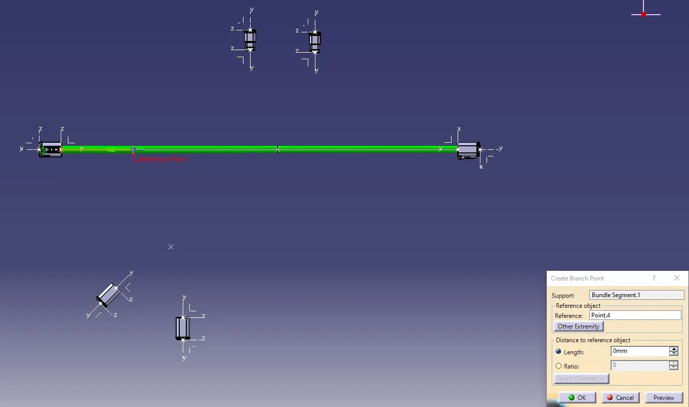
10. Then route the harness from the branch point to the connector.

11. Add protective covering available on catalogue on all branches by selecting protective covering command.