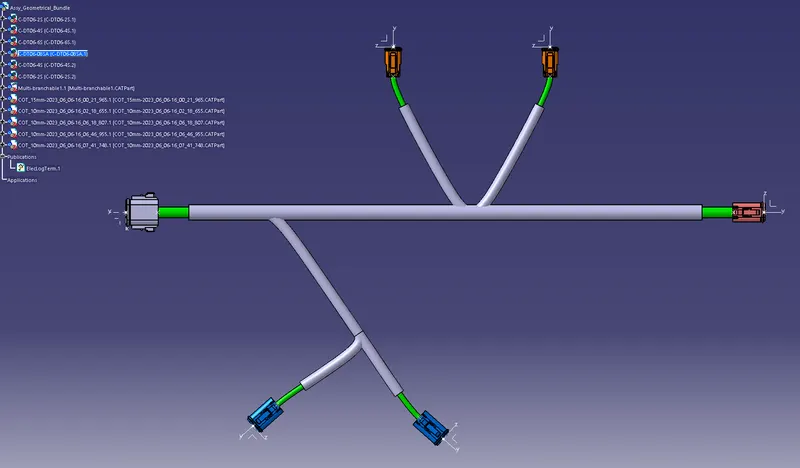
Wiring harness design in CATIA V5 - 3D modeling Week 4 Challenge
Objective: To create a wiring harness layout using the Electrical Workbench in CATIA V5.
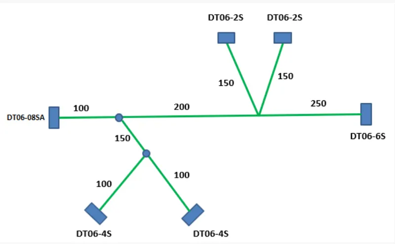
Theory:
Connector Definition:
Part Design:
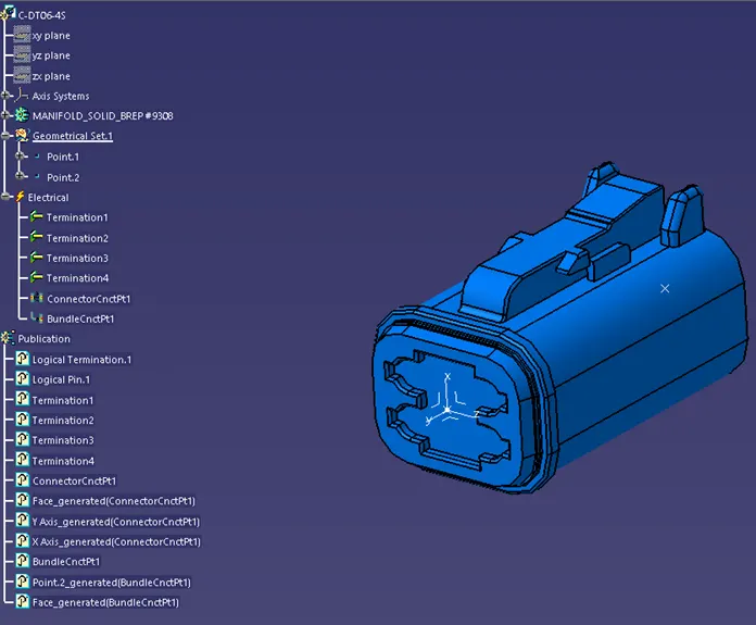
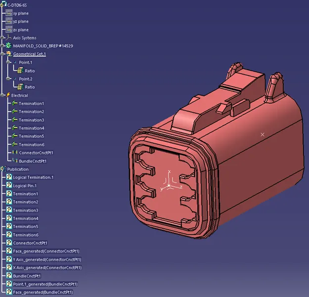
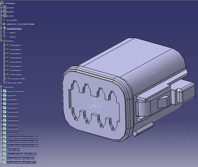
- Create two points one at the center of the mating side and the other at the center of the Bundle entry side.
- Create an axis system as shown in the image below at the mating side.
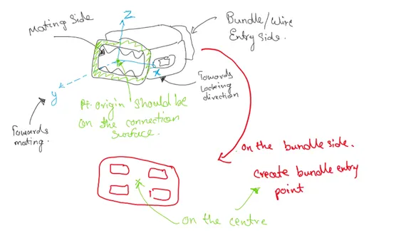
Electrical Part Design:
- Define the part as the connector.
- Define Connector Connection Point.
- Define Bundle Connection Point.
Procedure:
- Create a product and add the necessary electrically defined components into a product.
- Convert the product to an electrical assembly using ‘Geometrical Bundle’ command.
- Position the components to their position as per the input locations given.
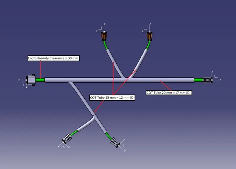
- Create routing using the ‘Multi-Branchable Document’ command. For routing select the appropriate diameter. Define the route by clicking on the two components as required.
- Add the protective coverings using the ‘Protective Covering’ command.
- Provide necessary clearance on the connector ends for the protective coverings.
Results:
Electrically Defined Connectors:
DT06-2S
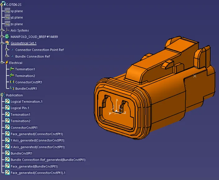
DT06-4S
DT06-6S
DT06-08SA
Complete Wiring Harness Routing:
Conclusion:
Hence, we have successfully created the wiring harness routing using the Electrical Workbench in CATIA V5.