Wiring harness design in CATIA V5 - 3D modeling Week 4 Challenge
Wiring Harness Design
Aim:
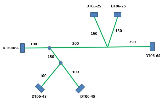
Route the following harness layout in Electrical workbench. Make assumption for harness bundle diameters. Use Following connectors as shown in layout diagram.
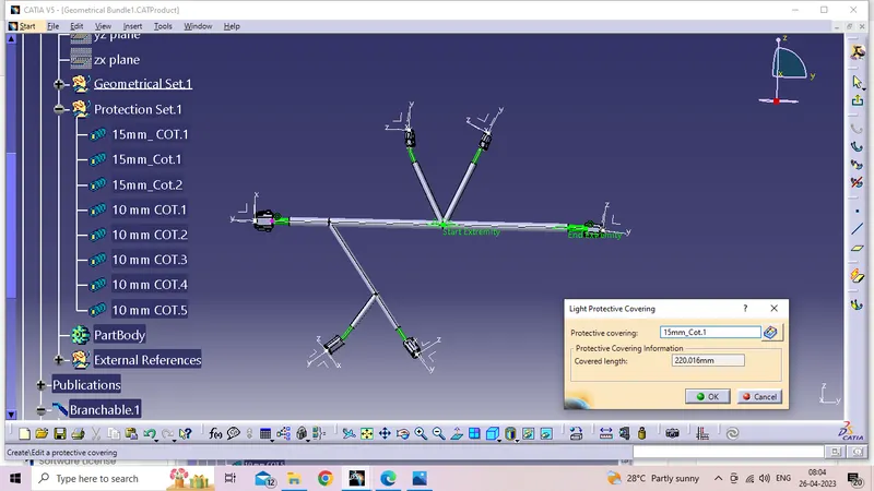
Add protective covering on all branches connected to DT06-2S & DT06-4S connectors. Keep end extremity at 30mm (from connectors end)
- DT06-4S
- DT06-6S
- DT06-2S
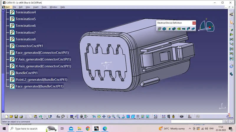
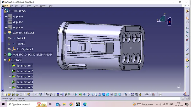
- DT06-08SA
DT06-08SA:
- Download DT06-08SA stp file into Catia v5
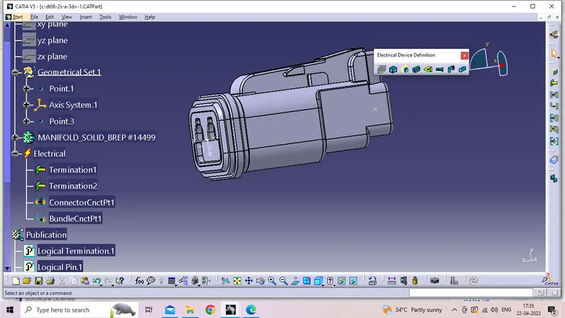
- Create a point for Connector connection point &Bunndle entry point.
- provide axis system for connector connection point.Y Aixs should be pointing towards the front face of the conectors,X axis should be pointing towards to the locking mechanicm for the clip ,Z axis for should be pointing across conectors from right to left.
- Define electrical equipment.
- Add into the Catlougue for Connectors.
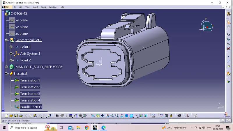
 DT06-4S:
- Download DT06-4S stp file into Catia v5
- Create a point for Connector connection point &Bunndle entry point.
- provide axis system for connector connection point.Y Aixs should be pointing towards the front face of the conectors,X axis should be pointing towards to the locking mechanicm for the clip ,Z axis for should be pointing across conectors from right to left.
- Define electrical equipment.
- Add into the Catlougue for Connectors.
 DT06-6S;
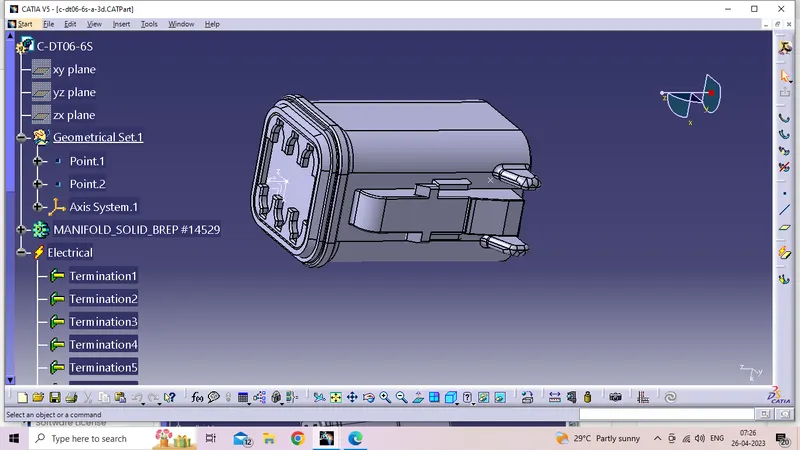
- Download DT06-6S stp file into Catia v5
- Create a point for Connector connection point &Bunndle entry point.
- provide axis system for connector connection point.Y Aixs should be pointing towards the front face of the conectors,X axis should be pointing towards to the locking mechanicm for the clip ,Z axis for should be pointing across conectors from right to left.
- Define electrical equipment.
- Add into the Catlougue for Connectors.
DT06-2S;
- Download DT06-2S stp file into Catia v5
- Create a point for Connector connection point &Bunndle entry point.
- provide axis system for connector connection point.Y Aixs should be pointing towards the front face of the conectors,X axis should be pointing towards to the locking mechanicm for the clip ,Z axis for should be pointing across conectors from right to left.
- Define electrical equipment.
- Add into the Catlougue for Connectors.
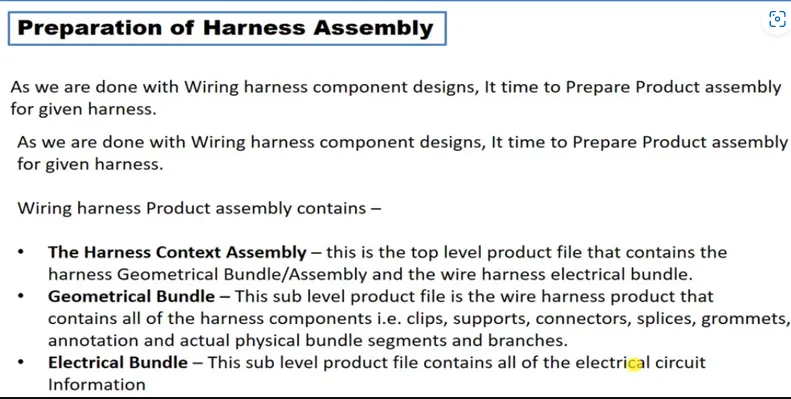
Preparation of Harness Assembly:
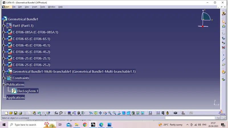
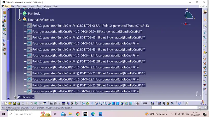
Add the all connectors which are electricaly defined to the Geomteric bundle assembly.
Then define this Geomteric bundle assembly as electricaly, for that we need to switch to Electric harness assembly workbench.
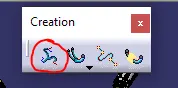
select Geometric Bundle then click on Geomteric bundle assembly (In specification Tree)
Now, to position all the connector as given in input file,
Create enviroment on which the bundle assembly will be placed.
After given dimensions draw the sketch into part body
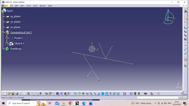
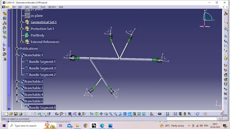
After all the connectors position into the paricular place by using Manupulation after that Constrains.
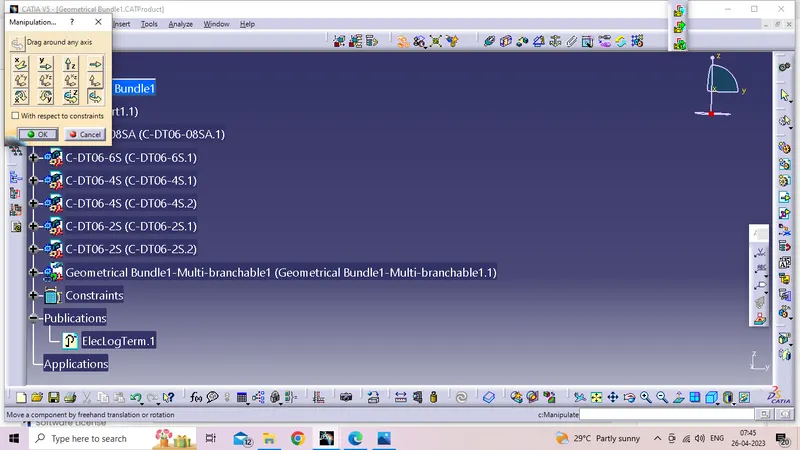
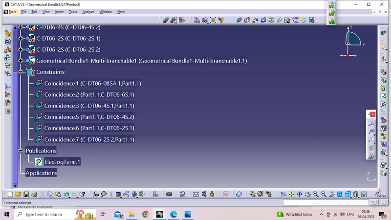
After completing the positioing jump into Wiring Harness Assembly work bench.
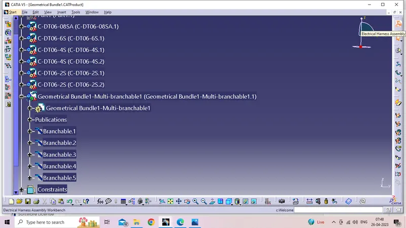
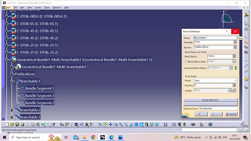
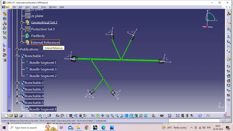
- Difine the Bunndle segments.
- Define route definitions.
- Define add brench points.
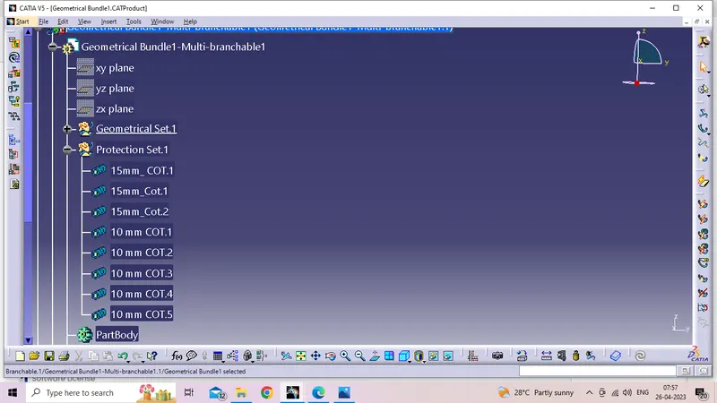
Add protective coverings.
Difine end Extrimity limits.