Wiring harness design in CATIA V5 - 3D modeling Week 4 Challenge
Aim:
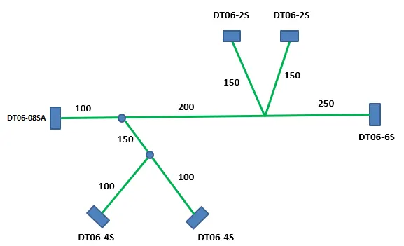
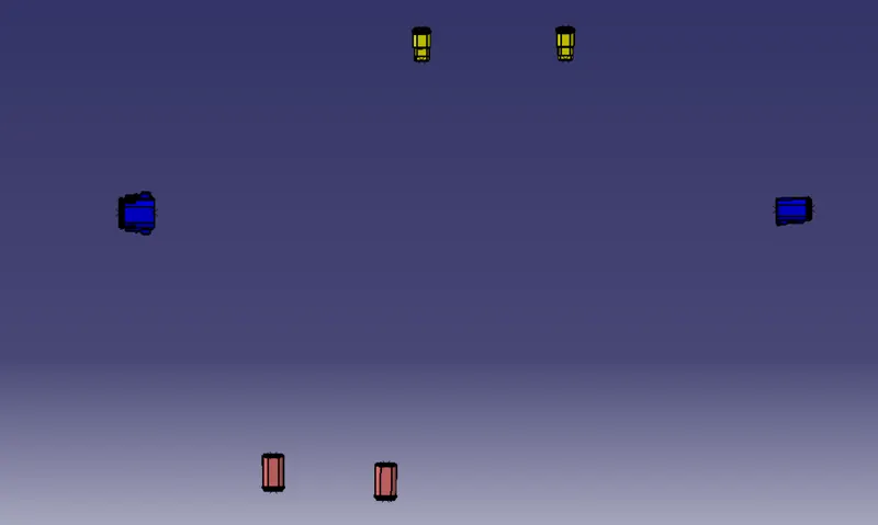
- To Route the following harness layout in Electrical workbench. Make assumption for harness bundle diameters. Use Following connectors as shown in layout diagram.
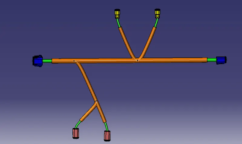
- Add protective covering on all branches connected to DT06-2S & DT06-4S connectors. Keep end extremity at 30mm (from connectors end)
-
Download connector 3D data from www.te.com
- DT06-4S
- DT06-6S
- DT06-2S
- DT06-08SA
1.DT06-2S
Step-1:
- Create the required Geomterical parts for the connectors
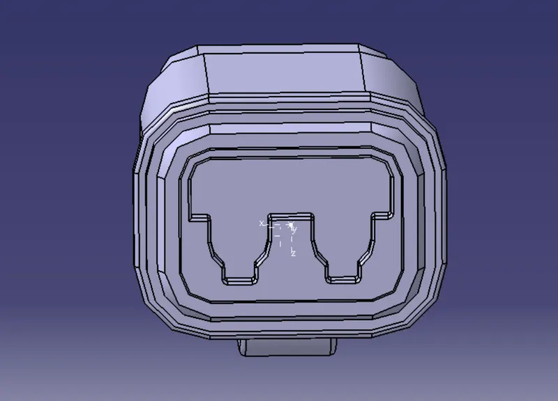
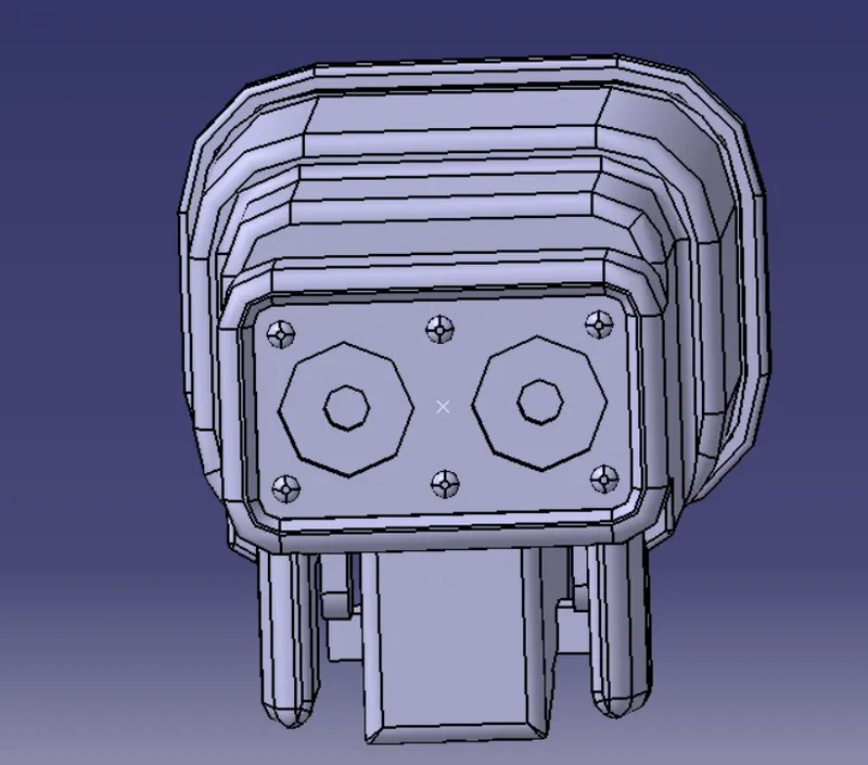
- Define the Bundle side and connector side and create the midpoint and axis for the required sides.
Connector side:
Bundle side:
Step-2:
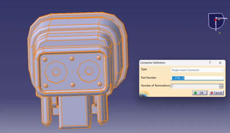
- Navigate to Electrical part workbench
- Define the part as connector
Step-3:
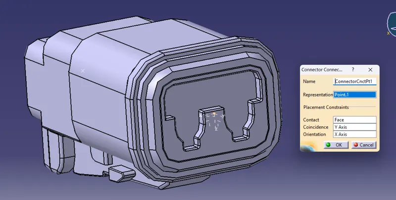
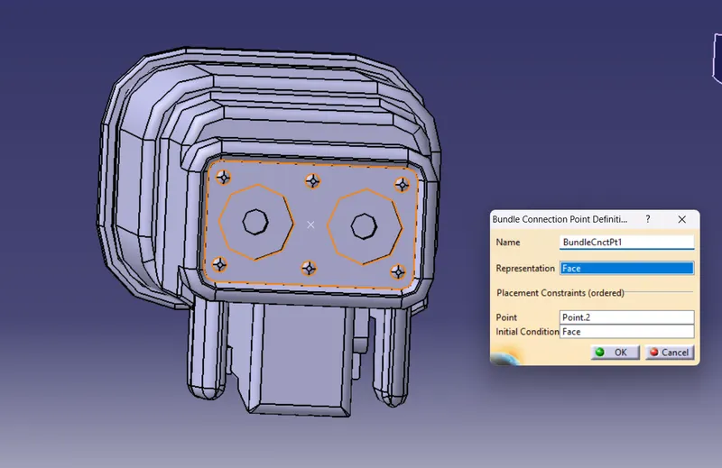
- Define the connector connection point and bundle connection point
connector connection point:
bundle connection point:
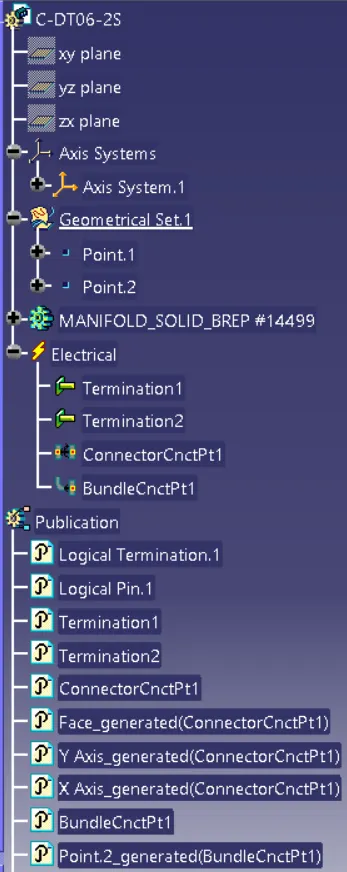
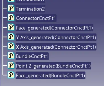
Tree Structure:
2.DT06-4S:
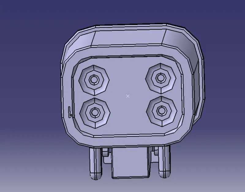
Step-1:
- Create the required Geomterical parts for the connectors
- Define the Bundle side and connector side and create the midpoint and axis for the required sides.
Connector side:
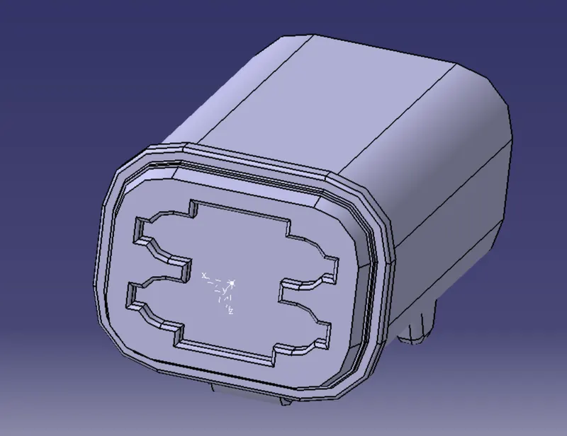
Bundle side:
Step-2:
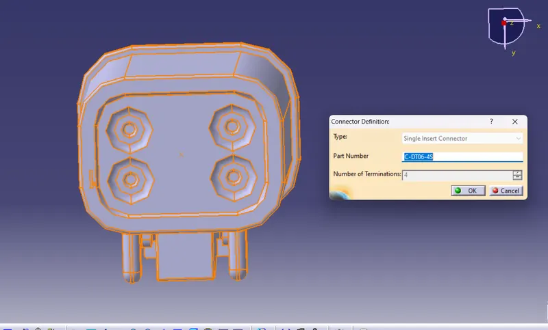
- Navigate to Electrical part workbench
- Define the part as connector
Step-3:
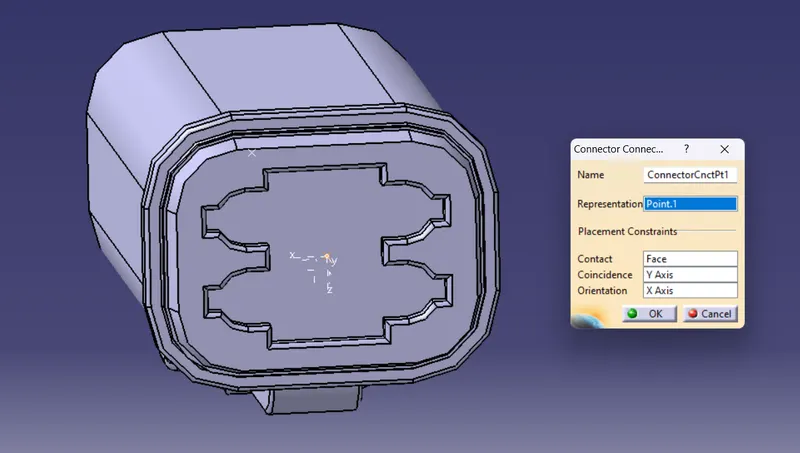
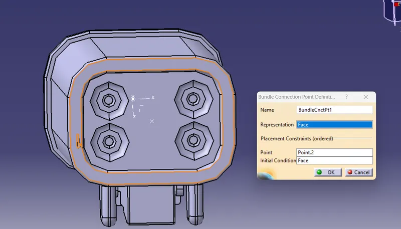
- Define the connector connection point and bundle connection point
connector connection point:
bundle connection point:
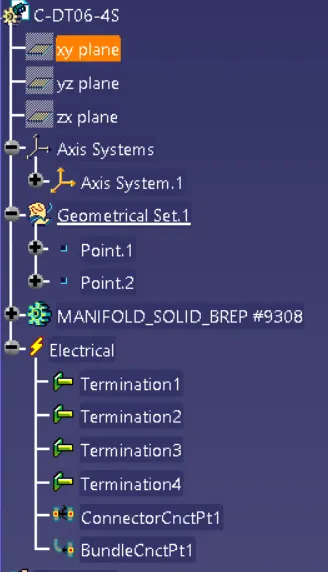
Tree Structure:
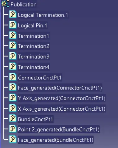
3.C-DT06-6S
Step-1:
- Create the required Geomterical parts for the connectors
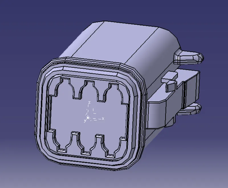
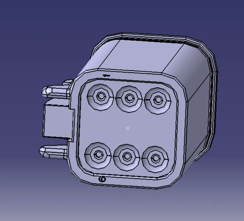
- Define the Bundle side and connector side and create the midpoint and axis for the required sides.
Connector side:
Bundle side:
Step-2:
- Navigate to Electrical part workbench
- Define the part as connector
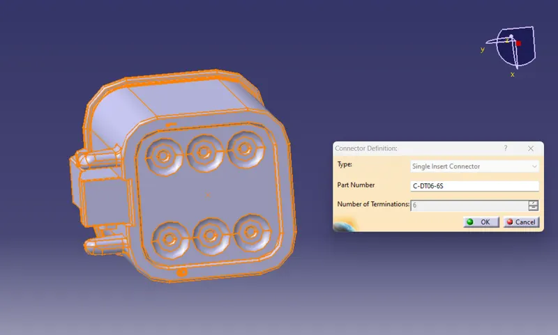
Step-3:
- Define the connector connection point and bundle connection point
connector connection point:
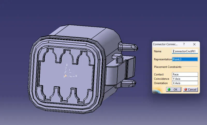
bundle connection point:
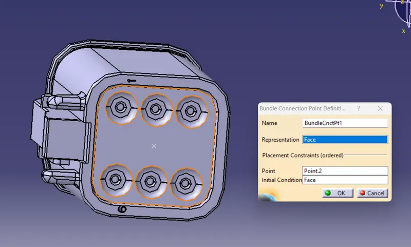
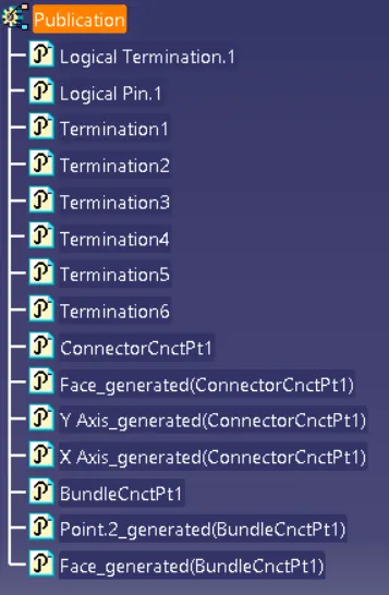
Tree Structure:
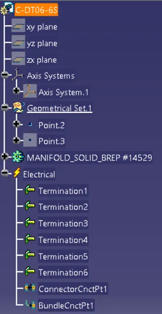
4.DT06-08SA:
Step-1:
- Create the required Geomterical parts for the connectors
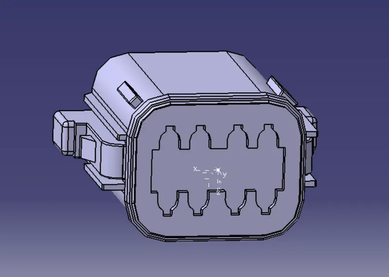
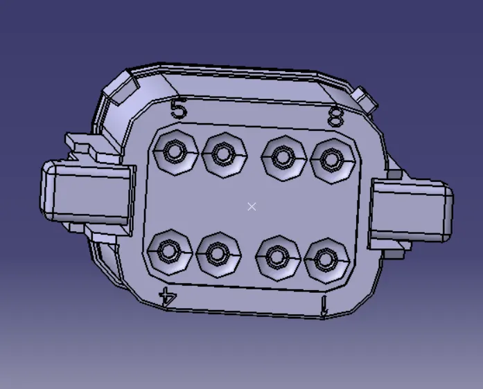
- Define the Bundle side and connector side and create the midpoint and axis for the required sides.
Connector side:
Bundle side:
Step-2:
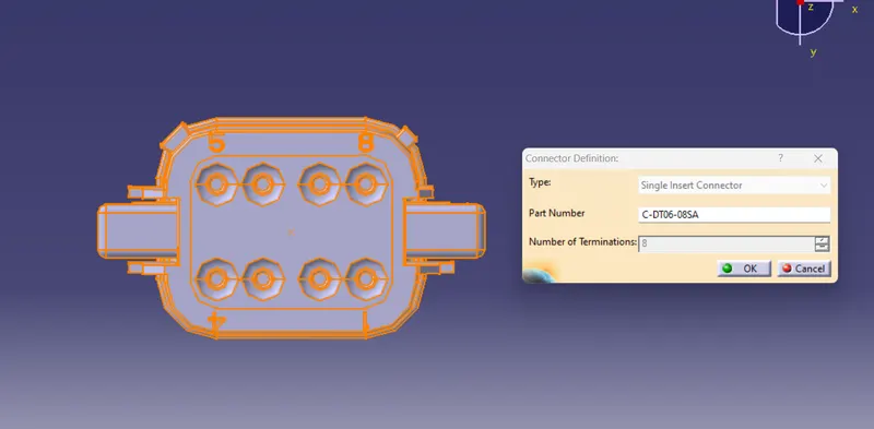
- Navigate to Electrical part workbench
- Define the part as connector
Step-3:
- Define the connector connection point and bundle connection point
connector connection point:
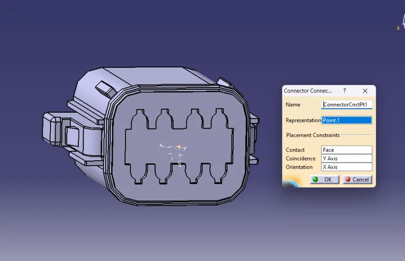
bundle connection point:
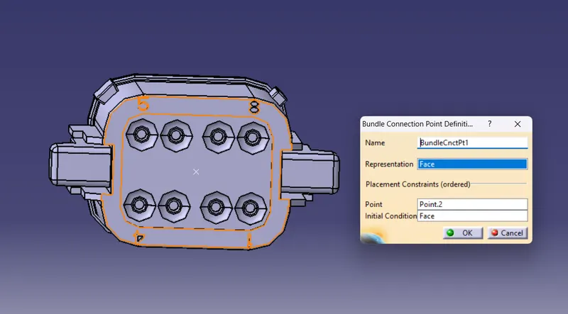
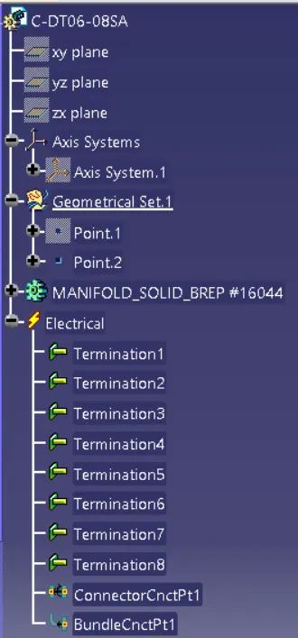
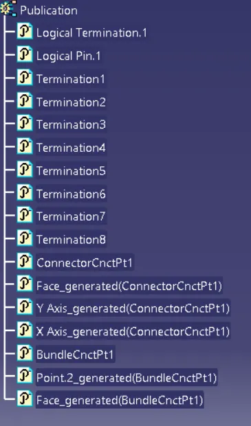
Tree Structure:
- After Defining the electrical properties save all the connectors in catalogue
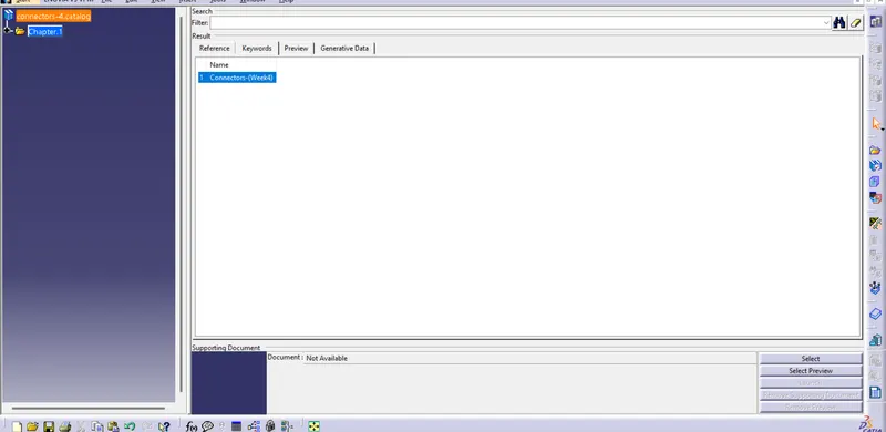
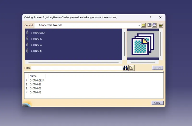
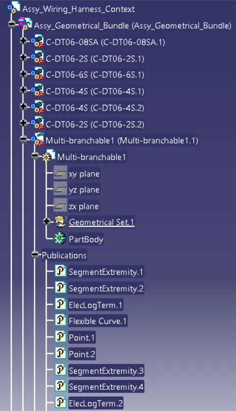
- Add the all connectors which are electricaly defined to the Geomteric bundle assembly.
- Navigate to Electrical Harness Assembly and determine geometric bundle to the assembly.

Position the connectors as per the given Diagram:
Create the wire harness bundle segments:
- Click on Branch defination and then click on route definition and select connectors in between we want to create branch.
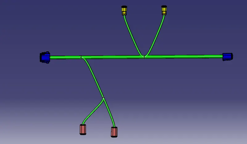
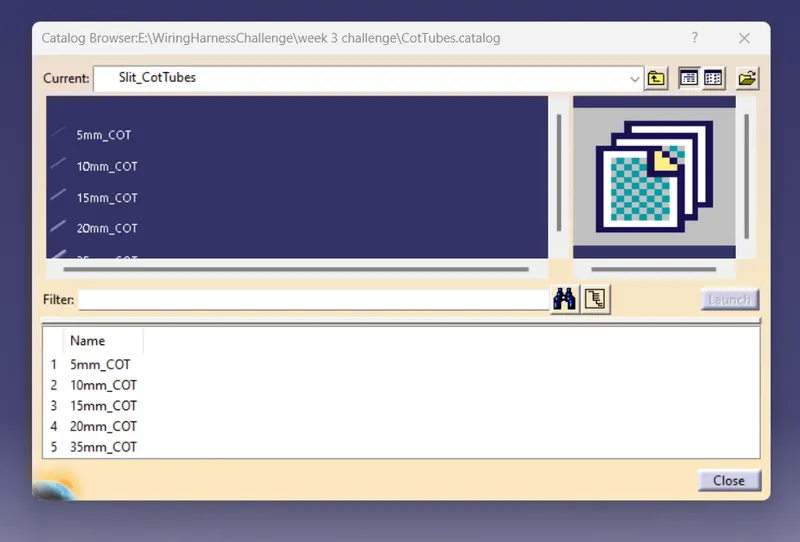
select protective covering then select branch - select catalog - select approprite slit cot tubes - give extrimity at start and end (30mm) :
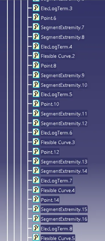
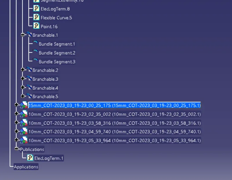
Tree Structure: