Wiring harness design in CATIA V5 - 3D modeling Week 4 Challenge
Wiring harness design in CATIA V5 - 3D modeling Week 4 Challenge
AIM:
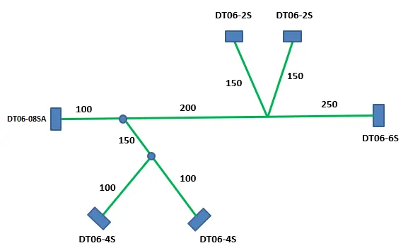
Route for the following harness layout is to be done in Electrical workbench. Make assumption for harness bundle diameters. Following connectors as shown in layout diagram is to be used. protective covering on all branches connected to DT06-2S & DT06-4S connectors should be added. End extremity at 30mm should be added(from connectors end)
SOLUTION :
- All the Connectors below are downloaded from te.com
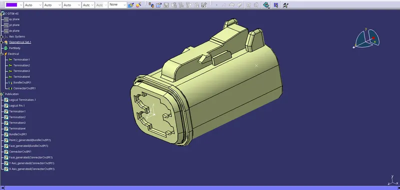
- DT06-4S
- DT06-6S
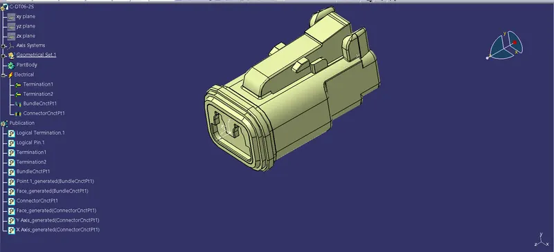
- DT06-2S
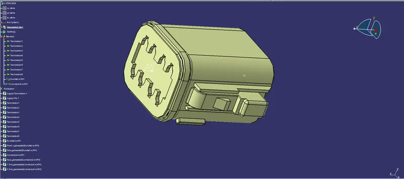
- DT06-08SA
- We have downloaded all the igs zip files

- All the files are extracted

- Open the CATIA software and convert the files to CAT parts

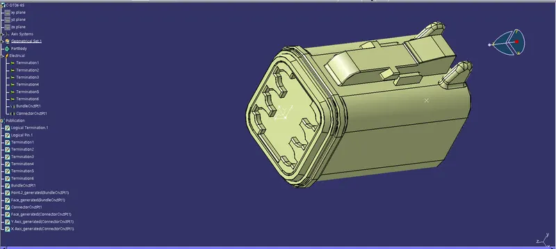
- All the Connectors are electricaly defined with the below steps
- Part body is opened and points are created for bundle entry
- Mating points are also created along with the axis definition
- we then switch to electrical part design
- We define the parts as connectors
- We define the point and budle entry point
- Connection connector point is also made.
- This is done for all the four connectors.
- Hence it is electricaly defined.
- We then create a catalog for this challenge and all the connectors.
- Here are few photos of the steps.
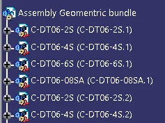
- New product is opened and it is named as Assembly Harness

- And new component is opened under this as Geomentric bundle
- It is defined as geomentric bundle. Note the symbol has changed now.

- We add all the connectors here
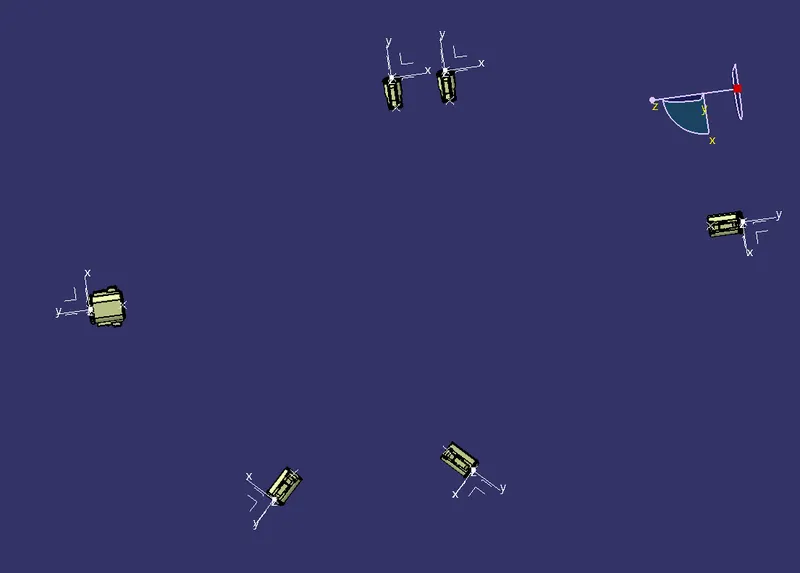
- The connectors are aligned as per the photo given.
- We use various commands to rotate and move the connectors
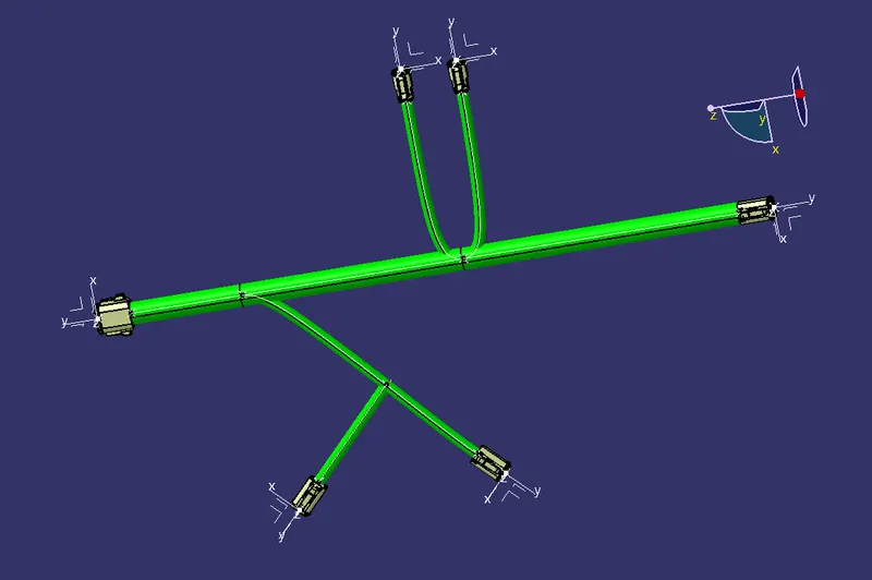
- Multi branchable is added to the geomentrical bundle
- Connectors are routed with the branch bundle by clicking the connectors
- To add sub branches Branch point is created on the main line.
- Then branches are routed to the connectors as per the question
- Tangency are changed to give a good curvature to the harness bundle
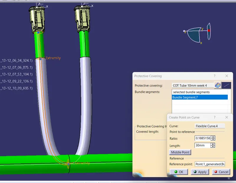
- Protective covering is applied to the branches
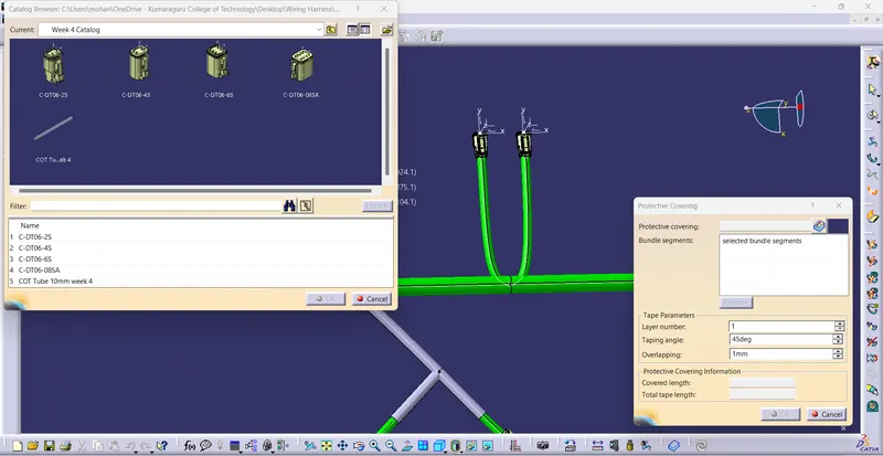
- New COT Tube is created and added to our catalog previuosly created
- It is then applied to the branches by clicking the branch and applying the COT tube.
- End extrimity is kept 30mm away from the connector as said in the question
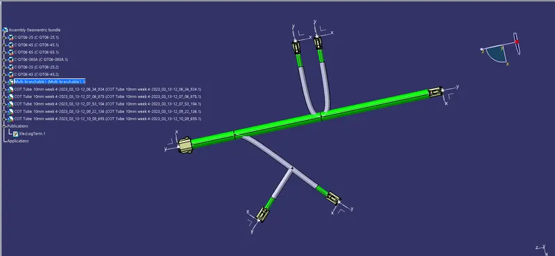
RESULT :
Route for the following harness layout is done in Electrical workbench. Following connectors as shown in layout diagram is used. protective covering on all branches connected to DT06-2S & DT06-4S connectors is added. End extremity at 30mm is added(from connectors end)