Wiring harness design in CATIA V5 - 3D modeling Week 4 Challenge
Objectives:
- Define the Mechanical connectors electrcally and store it in the Catalogue.
- Prepare the bundle routing for the connectors and orient the bundle in proper direction using rotate command
- Add the protective coverings to the bundles created
Answer:
Define the mechanical connectors Electrically:
- First step is to create the parameters of the mechanical connectors using mechanical part workbench.
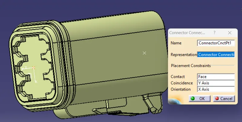
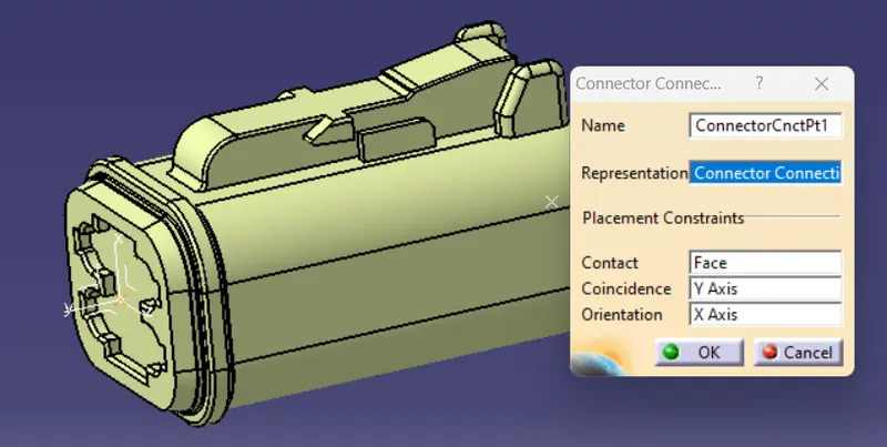
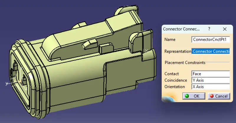
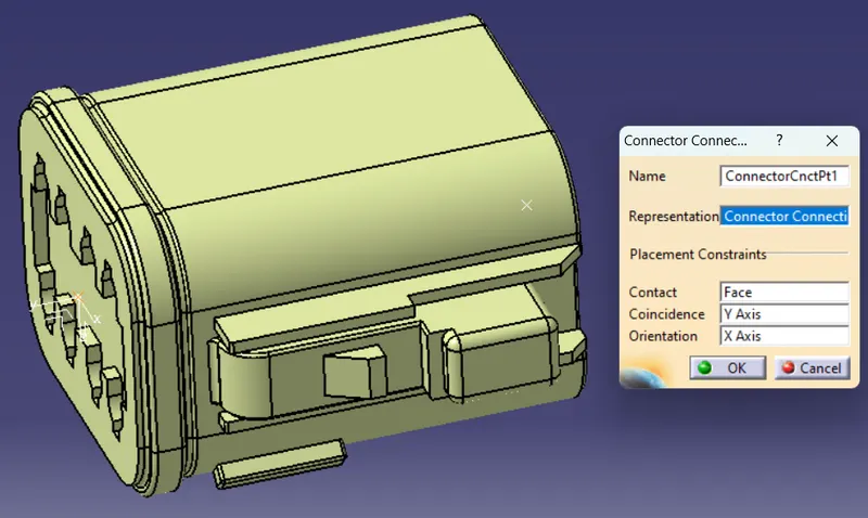
- Next step is to create bundle connection point and create connector connection point.
- Then create connector connection axis, where Y axis facing towards connector entry and X axis toward locking mechanism.
- Then define the connectors electrically using electrical part workbench.
- First step is define the connector and terminals using connector option.
- Then Define bundle connection point option to define bundle entry position.
- Then Define connectot connector point option to define connector entry point.
Bundle Routing:
- Initial step for creating bundle routing is arranging the connectors as per the layout location.
- For the arrangement of the connecters created one rough layout as per given data using part design work bench and connected in the main bundle assembly
- Then add all the connectors in the geometrical bunde assembly file using existing file option or add using catalog browser option from part assembly workbench
- Then define the assembly by electrical using geometrical bundle option from electrical harness assembly workbench and select the assembly product file.
- Then put the connectors in the desired location using manipulation, snap and compass option from part assembly workbench
- After arranging the connectors in the desired location the next step is to create routing.
- For creating routing we have to select multi branchable document option from electrical harness assembly work bench.
- Then the multi branchable file is created, then the branch definition windows will pop up, there we have to put the diameter of the bundle.
- Then give the bundle bend radius ratio, after that open route definition option.
- There we have to select the required connectors for creating the bundle, we have to select 2 connectors in each bundles.
- Follow the above option to create new bundles in multi bundle segment.
- Add branch point option to create branch points in the bundle
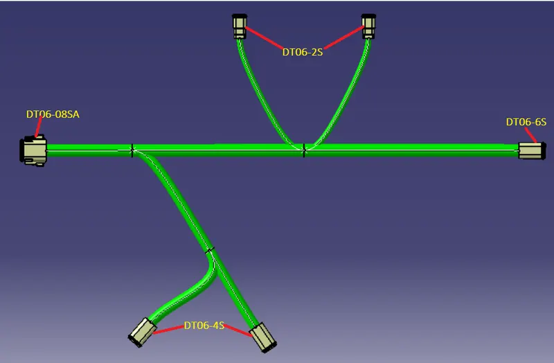
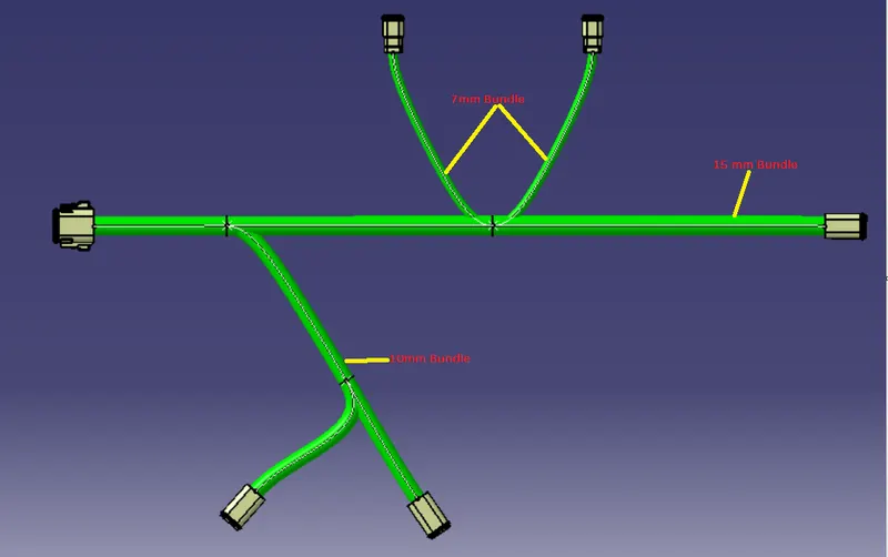
Add protective covering:
- After creating bundle of the connectors next step is to creating bundle protection corrogated tubes.
- For creating cot tubes in the bundle choose protective cover option and select the bundle segment for creating the cot tubes and choose the correct cot tubes from the catalog from the browse option, the put the end extrimity point at 30mm and click ok.
- Following steps to create protective covers of required bundle segments.
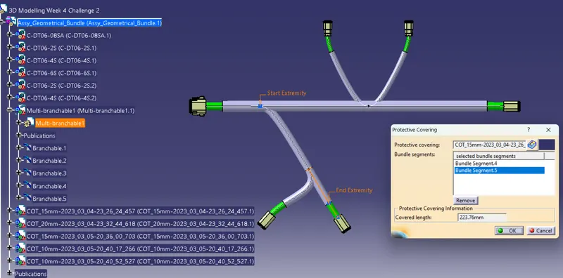
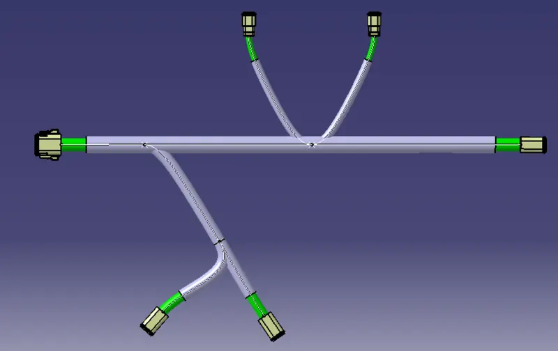
Conclusion:
Defined the Mechanical connectors to electrcally and stored it in the Catalogue. Then prepared the bundle routing for the connectors and orient the bundle in proper direction using rotate command and Added the protective coverings to the bundles and maintain the end extrimity at 30mm.