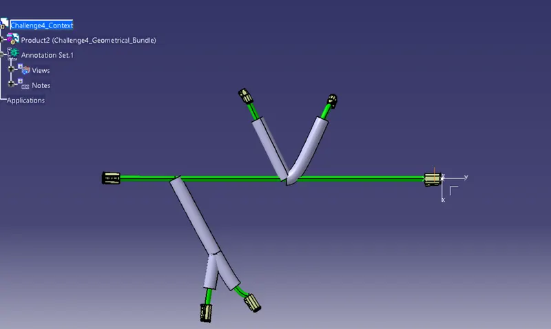
Wiring harness design in CATIA V5 - 3D modeling Week 4 Challenge
Answer:
The given Connector are first downloaded from the TE.com, the following connectors are
- DT06-4S
- DT06-6S
- DT06-2S
- DT06-08SA
And This connector are opened in the Catia V5 where we need to define them in Electrical
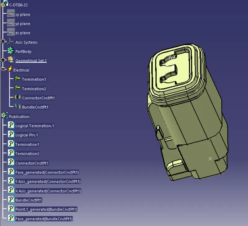
DT06-2S
WorkBench: Part Design
- First we need to create 2 points on the ends
- And on the connector connection side we need to create a Axis which will be usefull for the connector connection point
WorkBench: Electical Part Design
- In this workbench we need to define the component as a Connector
- And on the connector connection point is defined as well as bundle connection point
- Save the part
DT-06-4S
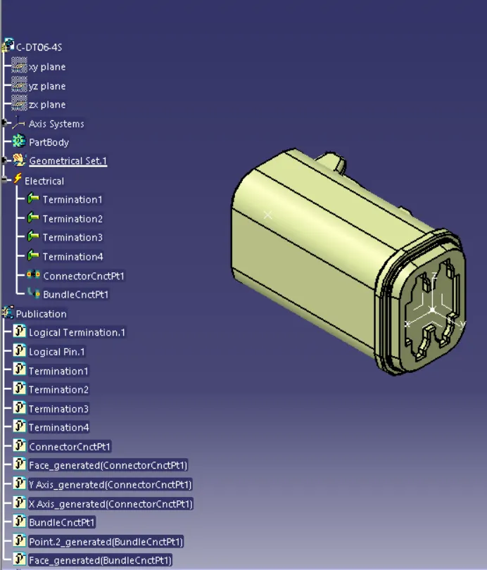
WorkBench: Part Design
- First we need to create 2 points on the ends
- And on the connector connection side we need to create a Axis which will be usefull for the connector connection point
WorkBench: Electical Part Design
- In this workbench we need to define the component as a Connector
- And on the connector connection point is defined as well as bundle connection point
- Save the part
DT-06-6S
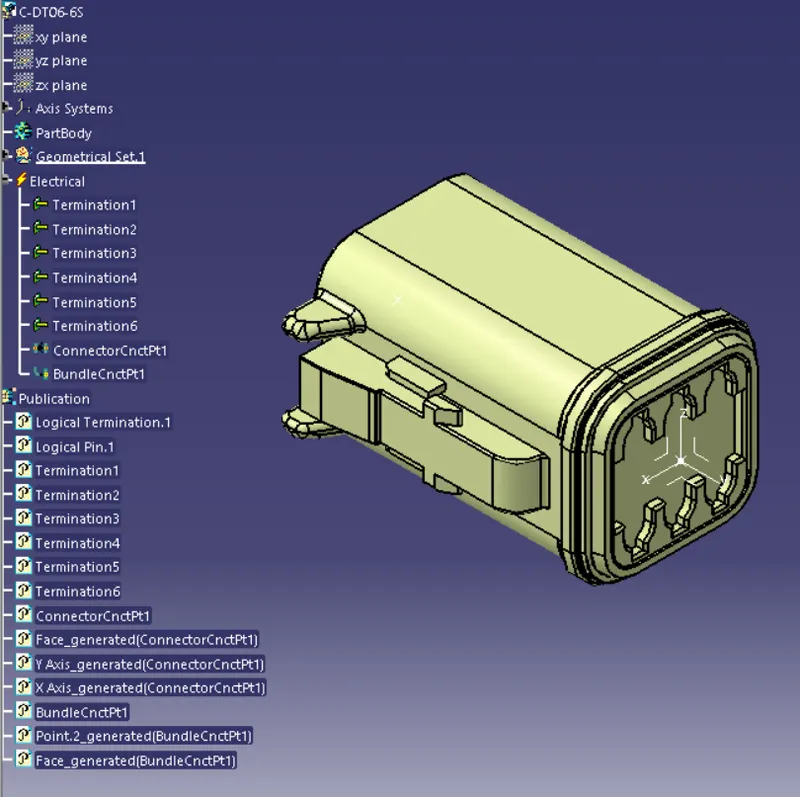
WorkBench: Part Design
- First we need to create 2 points on the ends
- And on the connector connection side we need to create a Axis which will be usefull for the connector connection point
WorkBench: Electical Part Design
- In this workbench we need to define the component as a Connector
- And on the connector connection point is defined as well as bundle connection point
- Save the part
DT-06-8SA
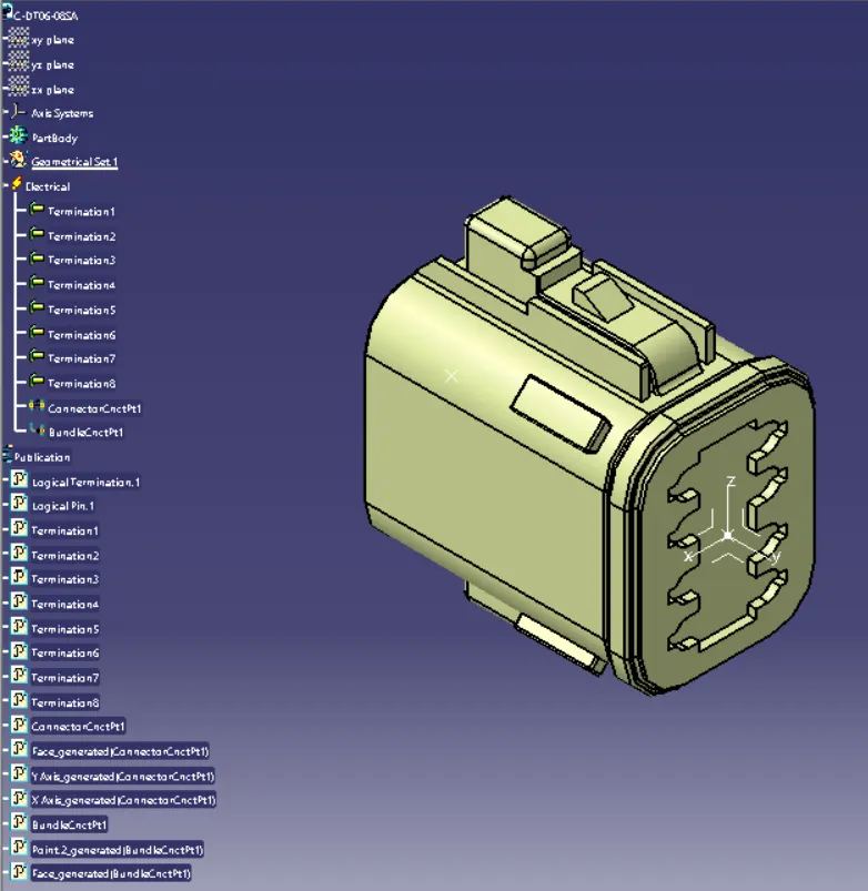
WorkBench: Part Design
- First we need to create 2 points on the ends
- And on the connector connection side we need to create a Axis which will be usefull for the connector connection point
WorkBench: Electical Part Design
- In this workbench we need to define the component as a Connector
- And on the connector connection point is defined as well as bundle connection point
- Save the part
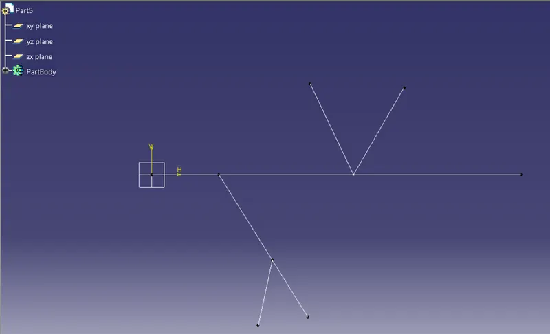
WorkBench : Part Design
This workbench is used to create the dimensions of the various connectors which are to be placed
- Go to the Sketcher option
- select the yz plane and draw the following lines as per the dimensions mentioned in the question
- Save the part
After defining all the 4 components as electrical we need to follow this steps
- Create a new Product and define it as the context file
- Create one more product within the context file and name it as Geometrical bundle
- Now copy all the 4 components in this file and also the part file where is drawing is available
- Now assembly the connectors to the desired locations
Now we need to switch to new workbench which is the Electrical Harness Installation
Workbench : Electrical Harness Installation
- Select the Geometrical bundle and select the Geometrical bundle product, now the product is Geometrical defined
- By using the Multi-branchable option we can start connecting the connectors
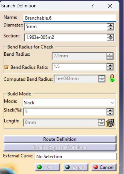
- By using the Route Defination option we can route all the connectors
- By using the Add branch Point option we can create a point so that we can connect the other 2 connectors of DT-06-4s and also the DT-06-2s
- Now we need to add the corragated tubes on the following 4 connectors
- from the catalague where we have saved various corragated tubes we can use them
- The end extremity is considered as 30mm from the connector