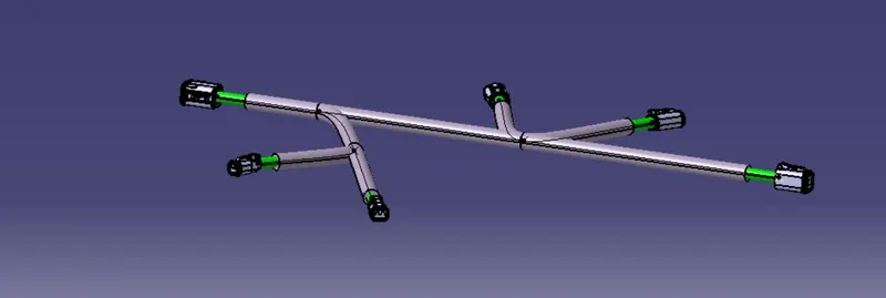
Wiring harness design in CATIA V5 - 3D modeling Week 4 Challenge
Aim:
Electrically defined the given connecters with the help of geometry, routing between connecters and apply corrugated tubes on the wires by the electrical wiring harness workbench
Introduction:
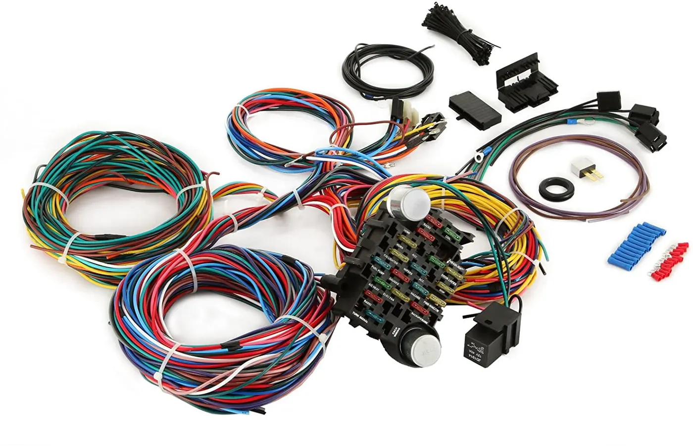
Wiring harness:
Systematic bound of electric wires and electric parts This process is doing in CAD for assembly and production. E.g.: wire, connecters, back shell etc
Connecters:
It is connecting electrically one function with another or connect the wires.

Wire Buddle:
A compact group of electrical wires held together with special warping device. It connects the electricity one to another component. Inside copper and cotted with plastics like PVC, PP.
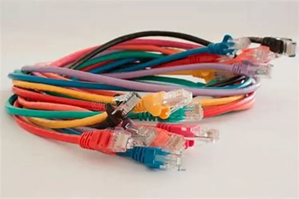
Corruglated tubes:
It is bellows shapes and flexible. It is using to product the wiring harness and give asthetic looks. It also made by platics.
Tools:
For electrically define some create some geometries and electrical part design tools.
Mechanical part work bench:
Point:
It indicates one location. This tool is used to create between two points in the centre of face.
Axis system:
It is fixed on a point and give X, Y, Z direction and plane in the location which is used to define and assemble the electrical parts.
Electrical part work bench:
Define connecters:
This option is used to define the connecter with buddle entry points. After this process CATIA will take the part as connecter.
Define mounding equipment:
This option is used to define as mounding equipment. After this process it take as mounding equipment.
Define connecter connection point:
This option is used to define the connecter connection point with the help representation, contact, coincident and orientation which are given by point, surface and axis system.
Define bundle connection point:
This option is used to define the bundle entry point of connecter with the help representation, contact, coincident and orientation which are given by point, surface and axis system.
Define cavity connection point:
This option is used to define the cavity connection point of connecter with the help representation, contact, coincident and orientation which are given by point, surface and axis system.
Define cavity:
This option is used to define the cavity connection point of mounding equipment with the help representation, contact, coincident and orientation which are given by point, surface and axis system.
Electrical assembly:
Connect electrical device:
This option available in electrical assembly bench. This option is used to connect the two electrical devices. Arter defines the electrical device if we click the part it automatically assemble with help of point, axis, face of surface from electrical define.
Disconnect electrical device:
This option is used to disconnect the two electrical devices from connected devices.
Electrical harness assembly:
Multi blanchable document:
This option is used to create the wires between the connecters. In this comment work bench different option is used to routing the wires.
Designing:
Define the Connecters:
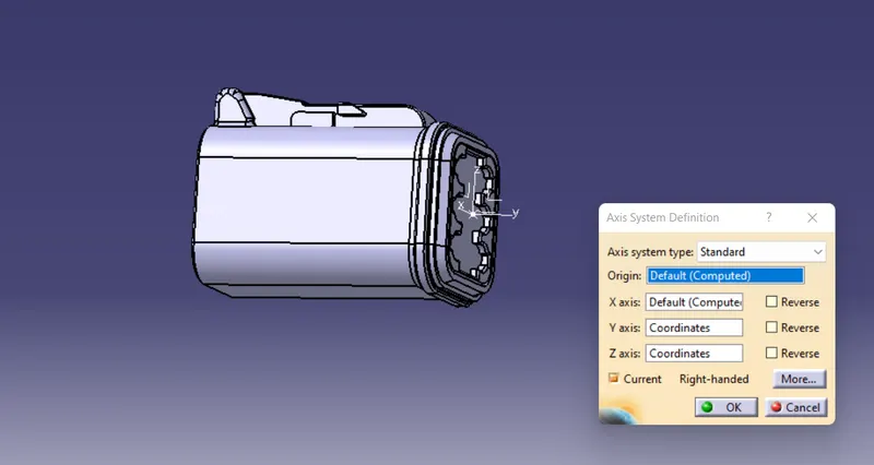
First create the geometry such as point, axis to define the electrical device.
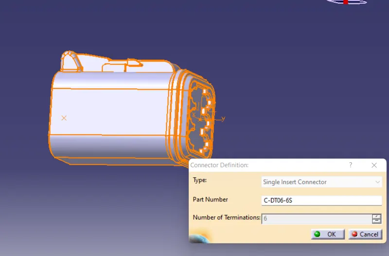
Then define the connecter.
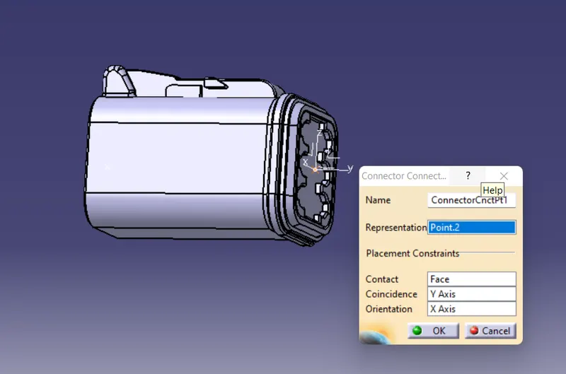
Then give connecter connection point.
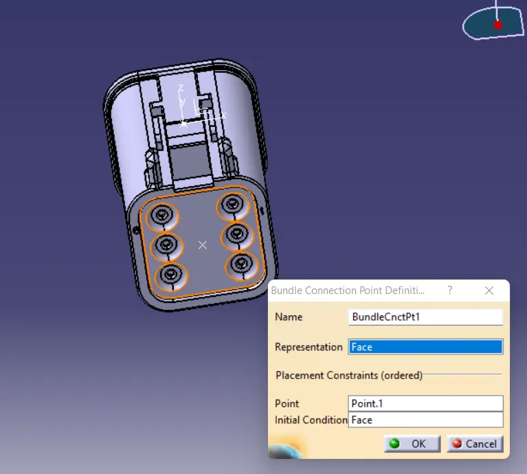
Finally, define bundle entry and save in catalogue. Same procedure is used to define the all connecters.
Create the base:
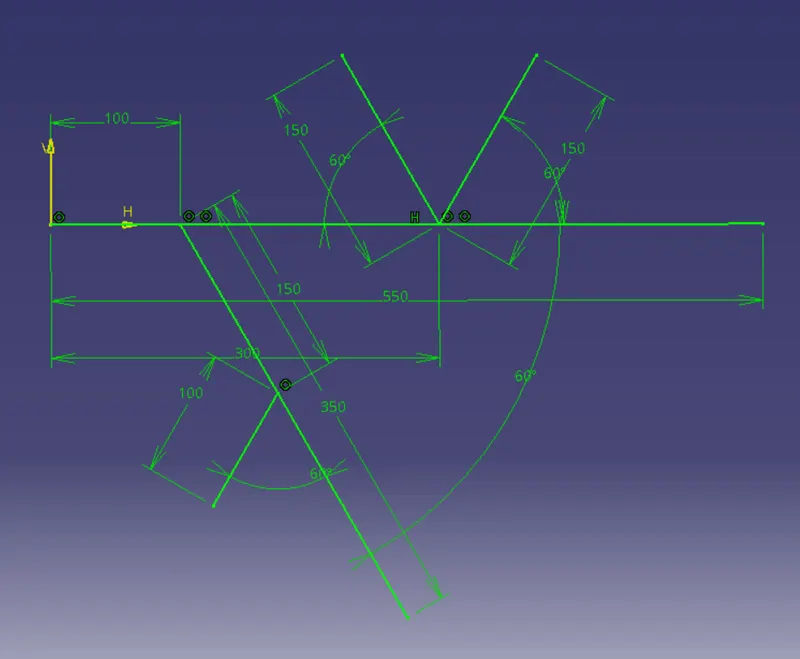
Draw the sketch and create the base for routing.
Routing:
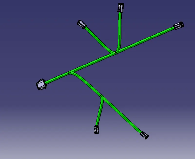
First arrange the all conecters in the edge of the sketch. Then Multi blanchable tool is used to create the wire between the connecters by the sketch.
Corrugated tubes applying:
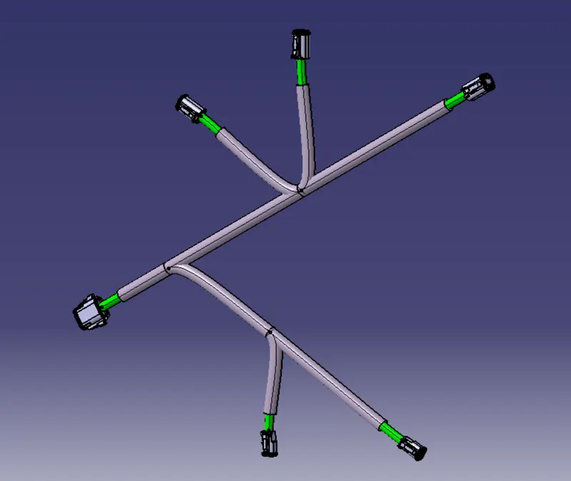
First create and save the corrugated tube in multiple size in catalogue. Then Production covering tool is used to apply by the cot tube catalogue.
Conclusion:
Given connecters are electrically defined and successfully routing between the connecters and give coregulated tubes for the routing wires by CATIA.