Wiring harness design in CATIA V5 - 3D modeling Week 4 Challenge
STEPS INVOLVED IN ROUTING THE GIVEN HARNESS LAYOUT
- Download the IGS file of the given connectors and open it in Catia V5
- Define the connector as an electrical part and define the bundle point, and connector connection point of all the connector
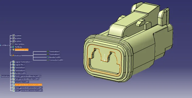
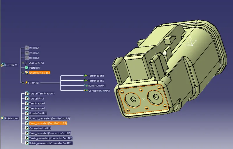
As we are done with electrical harness componenet designs , it is time to prepare product assembly
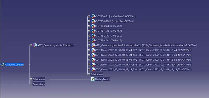
- Create a product file and name it as assembly wiring harness
- Create a sub product file and name it as Assembly geometric bundle
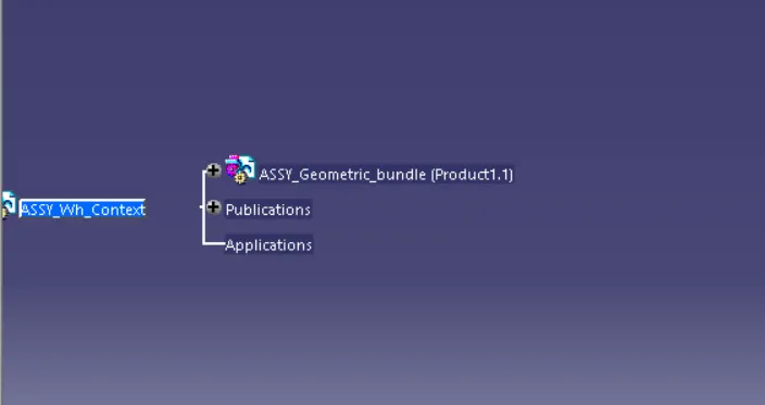
- Import the connectors in to the geometric bundle product file in electric harness assembly workbench
- Click on geometric bundle tool and then on geometric bundle product file
- make sure that every components are electrically defined
- Now switch to assembly design workbench and lets seperate the connectors and position them using suitable tool
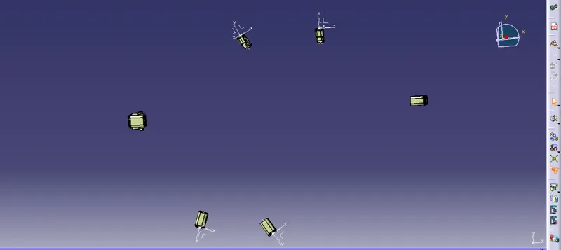
- We have a layout to position the connectors so lets create sketch of layout (part file)
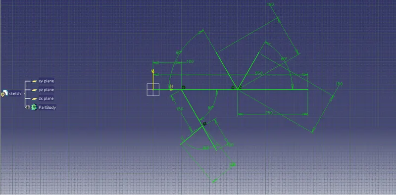
- So lets add this part file in to main product file
- position the connectors according to the layout using snap tool and compass
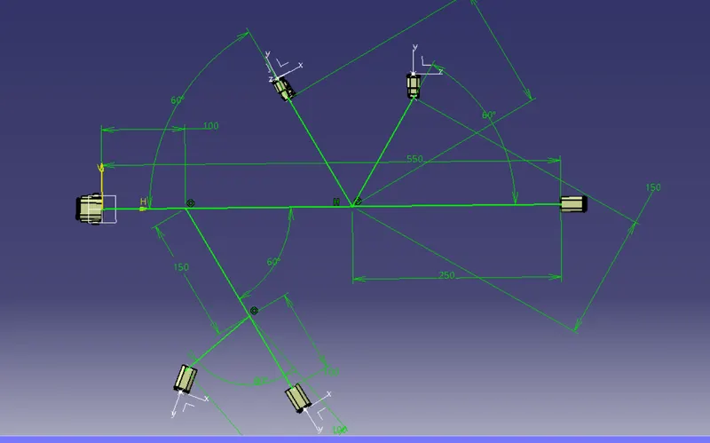
Now lets switch to electrical harness assembly
- Click on multi branchable document input the diameter, bend radius ratio, and click on route definition
- select the routing objects ( the 2 extreme connectors) .
- Click on add branch point tool to add branch choose length parameter and input the length
- repeat the process for making new new branch
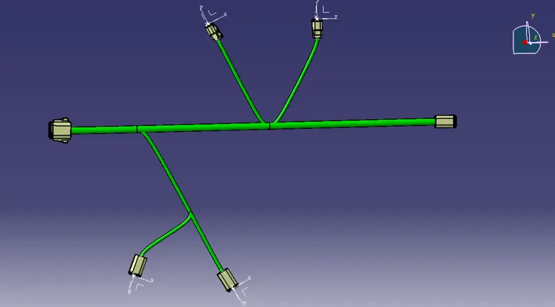
It is time to add the protective covering Corrugative tube
- Stay at electric harness assembly and click on add preotective covering
- Add the 15mm corrugated tube for the main branch and add extremity distance from connector as 30mm
- Then add 10mm corrugated tube to the branches
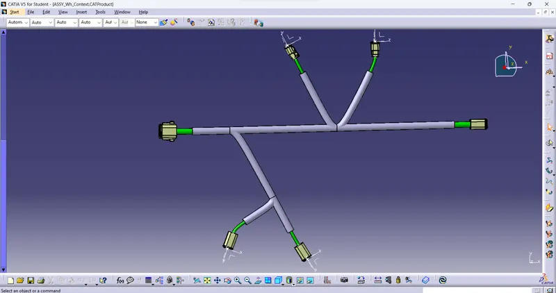
CONCLUSION
We have succesfully completed the routing process for the given electrical layout