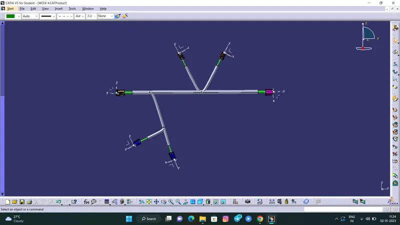
Wiring harness design in CATIA V5 - 3D modeling Week 4 Challenge
Aim:
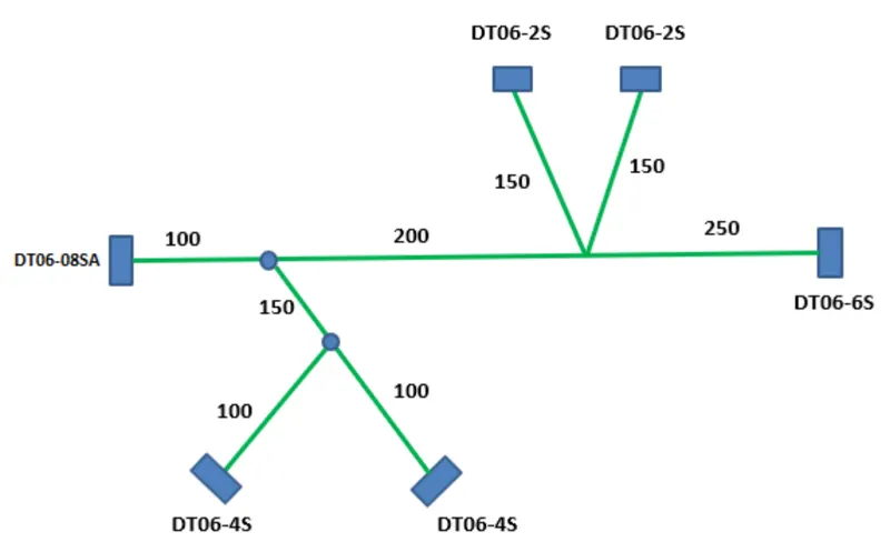
1) To Route the following harness layout in the Electrical workbench.
2) Add protective covering on all branches connected to DT06-2S & DT06-4S connectors.
Given:
CAD data of the following Connectors:
- DT06-4S
- DT06-6S
- DT06-2S
- DT06-08SA
Connectors Layout Design:
Steps to be followed:
1. Download connector 3D data from www.te.com
- DT06-4S
- DT06-6S
- DT06-2S
- DT06-08SA
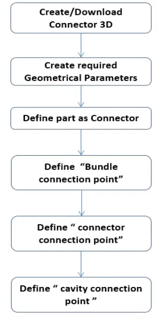
2. Convecting the Mechanical part into the Electrical part for that I had followed the following steps.
- DT06-2S
Connector connection point:
Create midpoint on the contact face which will be normal to wire bunddle insertion.
Craete Axis System with respect to the point which we have created and defining the axis direction as shown below,
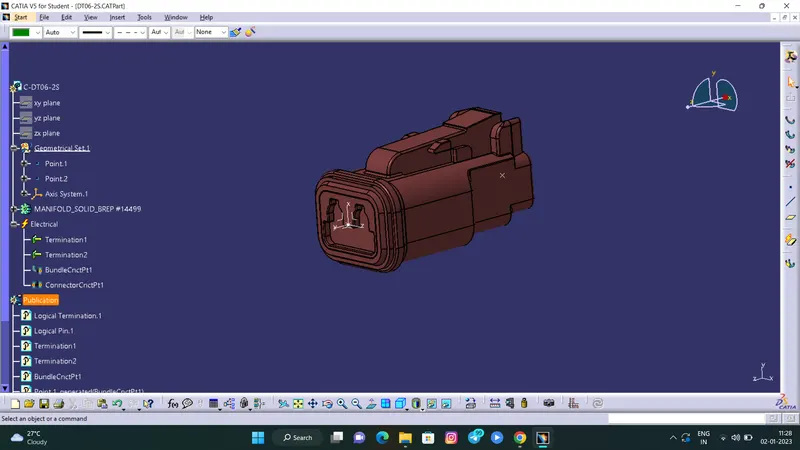
Bundle connection point:
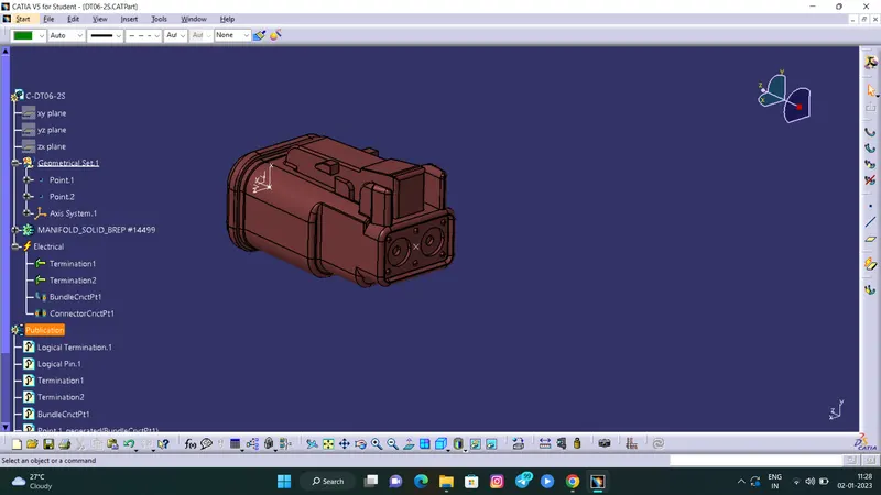
Switch to 'Electric Part Design'
Define the part as connector in catia, give no. of termination as 2 because we have 2 entry points for wire.
Define Bundle connection point
Define connector connection point
- DT06-4S
Connector connection point:
Create midpoint on the contact face which will be normal to wire bunddle insertion.
Craete Axis System with respect to the point which we have created and defining the axis direction as shown below,
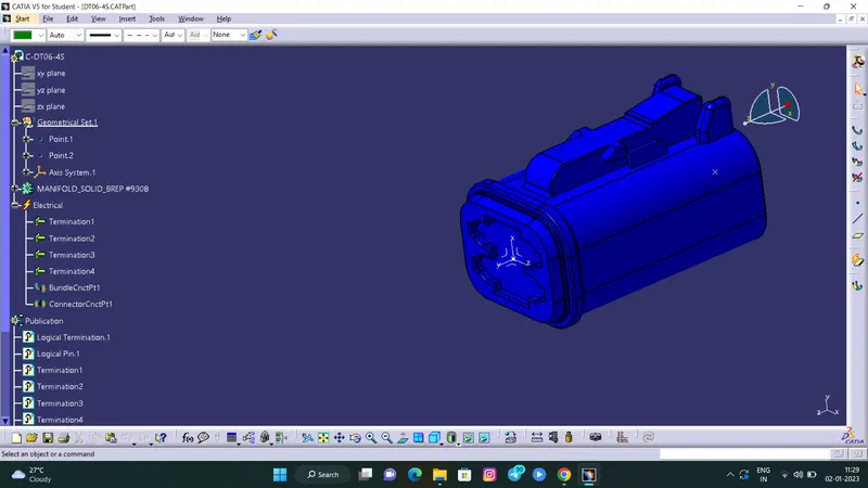
Bundle connection point:
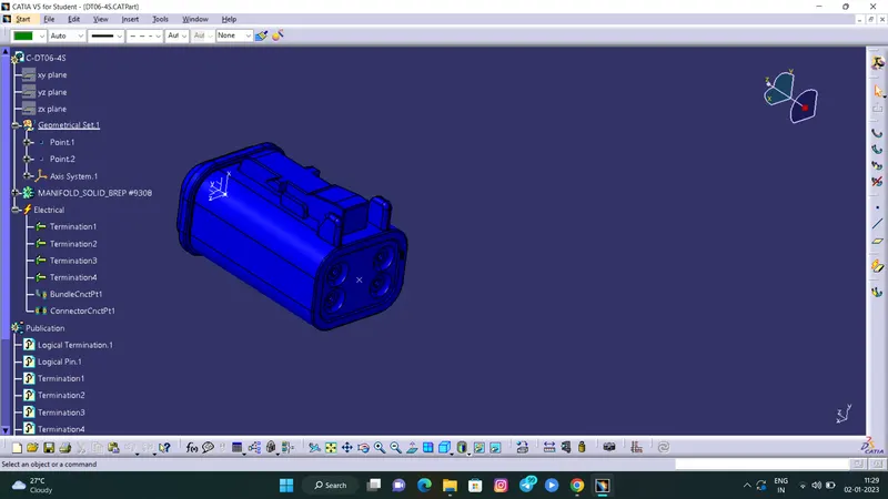
Switch to 'Electric Part Design'
Define the part as connector in catia, give no. of termination as 4 because we have 4 entry points for wire.
Define Bundle connection point
Define connector connection point
- DT06-6S
Connector connection point:
Create midpoint on the contact face which will be normal to wire bunddle insertion.
Craete Axis System with respect to the point which we have created and defining the axis direction as shown below,
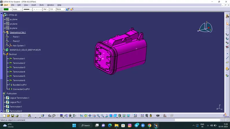
Bundle connection point:
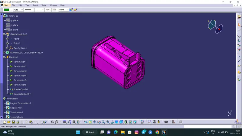
Switch to 'Electric Part Design'
Define the part as connector in catia, give no. of termination as 6 because we have 6 entry points for wire.
Define Bundle connection point
Define connector connection point
- DT06-08SA
Connector connection point:
Create midpoint on the contact face which will be normal to wire bunddle insertion.
Craete Axis System with respect to the point which we have created and defining the axis direction as shown below,
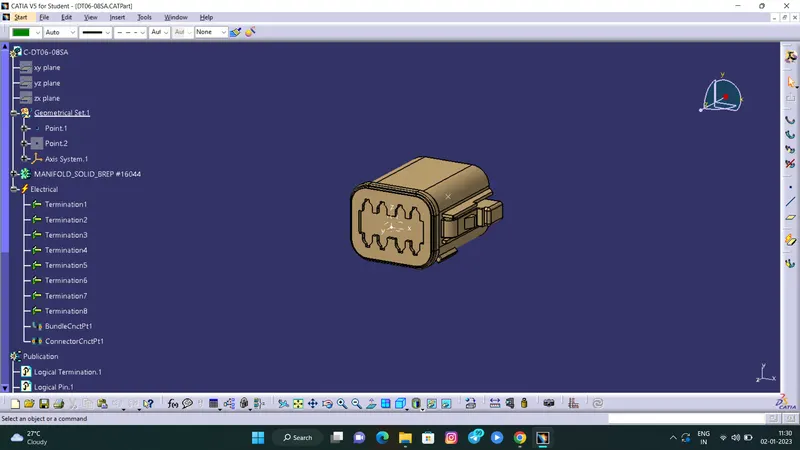
Bundle connection point:
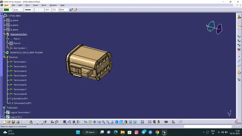
Switch to 'Electric Part Design'
Define the part as connector in catia, give no. of termination as 8 because we have 8 entry points for wire.
Define Bundle connection point
Define connector connection point
procedure to draw sketch
- Go to the file select new and then select part.
- In the part select any plane and draw the sketch by given mesaurement.
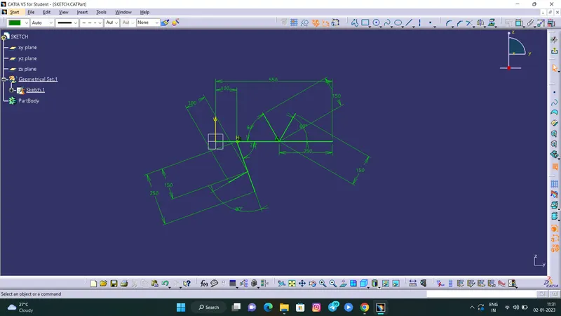
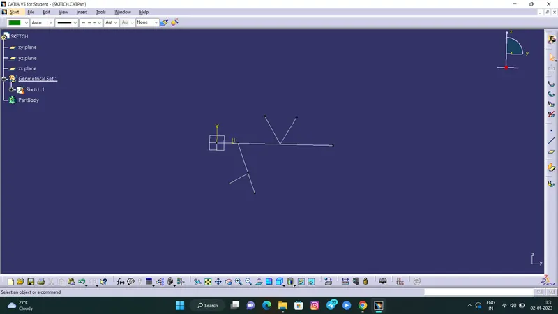
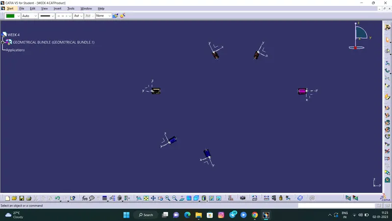
Arranging the Connectors by following the Layout
procedure for electrical harnees design.
- After doing arrangment go to electrical harness assembly for harness bundle connection.
- In this process the harness is connected to the connector.
- First go to the geometric bundle tool select on that then select on the part name on the tree .
- Now the part is electricaly defined.
- Now go to the bundle segment then select the route definition.
- After that select the connector which have to connect and select ok.
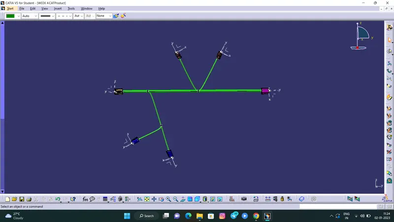
5.creating a protective covering