Wiring harness design in CATIA V5 - 3D modeling Week 4 Challenge
Objective :
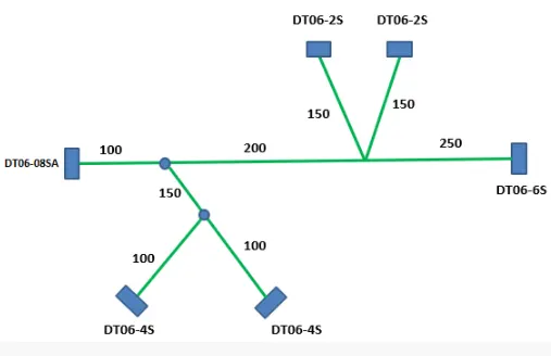
The objective of this project is to create the harness layout in the Electrical workbench and use the following connectors as shown in the layout diagram.
- DT06-4S
- DT06-6S
- DT06-2S
- DT06-08SA
Procedure :
- Initially, the mechanical model of the required connectors is downloaded.
- After that, the downloaded source file (Stp/Igs) is converted into CAT Part.
- Connector Definition :
1) Create/Download Connector 3D
2) Create required Geometrical Parameters
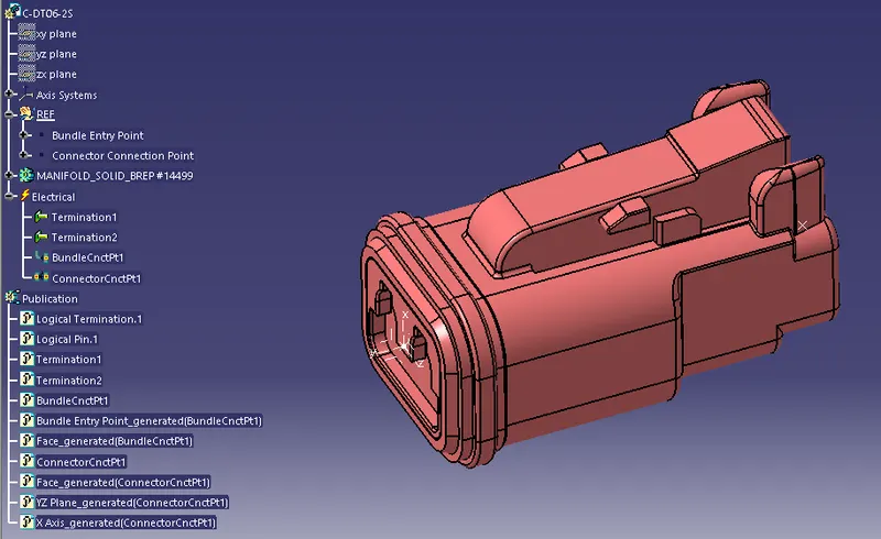
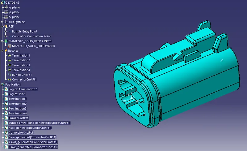
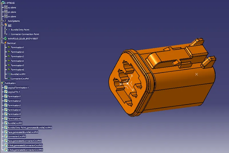
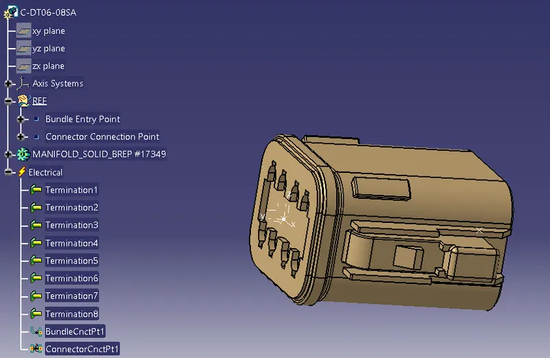
- In the third step the required reference points like Bundling entry point, Connector connection point, and Cavity connection point.
- Also, the required axis system for the Connector and Cavity is created.
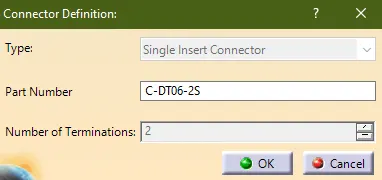
3) Define part as Connector
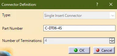
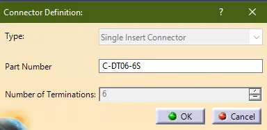
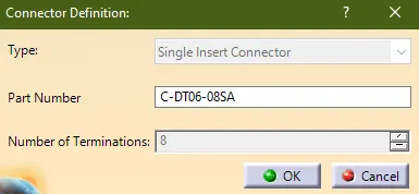
- The parts are defined as connectors by using the "define connector" option in CATIA
- While defining the connector, depending on the connector number of the terminal is mentioned.
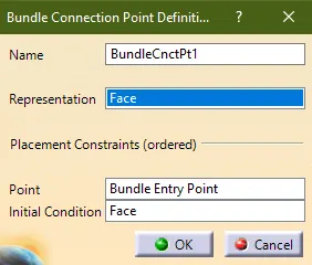
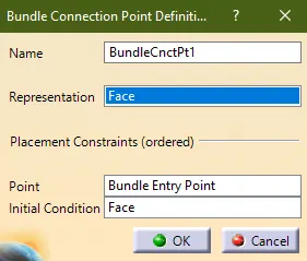
4) Define “Bundle connection point”
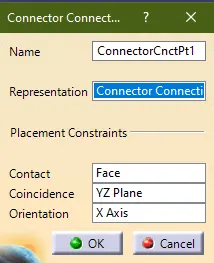
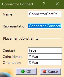
5) Define “ connector connection point”
Connector (C-DT06-2S)
Connector (C-DT06-4S)
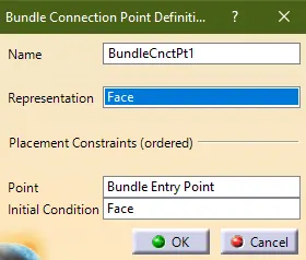
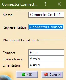
Connector (C-DT06-6S)
Connector (C-DT06-08SA)
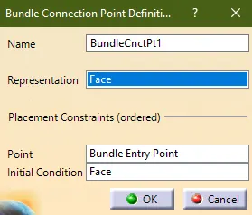
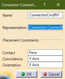
- After creating the connectors in all the connectors are inserted into the Assembly.
- The reference sketch is created as per the given image and then the connectors are properly placed in the required places.
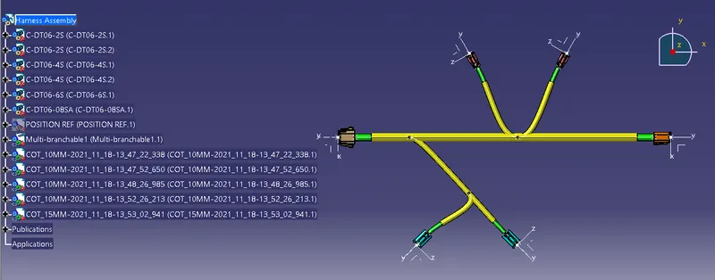
- Then, mechanical assembly is converted into the Harness assembly by using the "Geometrical Bundle" option available in the harness assembly.
- Multi-Branchabe is created and the branches are created as per the requirement.
- The Brachables are created by using the "Harness Installation workbench.
- Finally, the COT tubes are added to the branches. The required Cot tubes are already created and it is added into the Catlogue.
- From the catalog, the Cot tubes are added.
Multi-Branchable
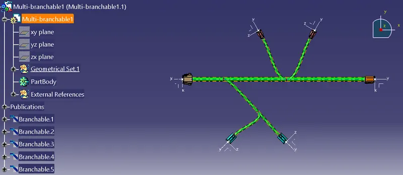
Harness Assembly