Wiring harness routing & packaging Rules Week 3 Challenge
Q1: Electrical Support (Clips/Clams/Support Parts) - P CLAMP
Objective :
The objective of this project is to create Electrical support (P CLAMP) and apply the electrical properties to the supports.
Procedure :
- Initially, the mechanical model of the required connectors is downloaded.
- After that, the downloaded source file (Stp/Igs) is converted into CAT Part.
- The geometrical parameters are applied to the electrical support.
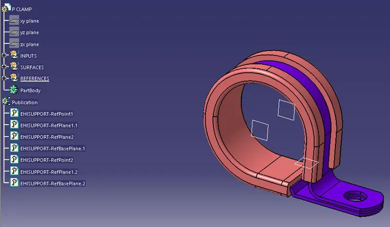
- After that, the entry point and plane are selected for the clamps use "define support option"
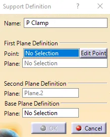
- Also, the base and exit planes are selected in the same way.
- The clamps will have 2 entry and exit points. Clamps are basically bi-directional.
Q2: Back Shell
Objective :
The objective of this project is to create a Backshell for connectors and apply the electrical properties to the same.
Procedure :
- Initially, the mechanical model of the required connectors is downloaded.
- After that, the downloaded source file (Stp/Igs) is converted into CAT Part.
- The geometrical parameters are applied to the back shell.
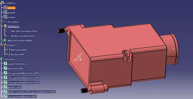
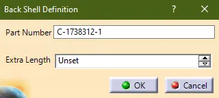
- Then, the part is defined as an electrical component by using the "Define Backshell" option.
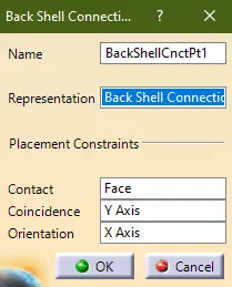
- After defining the part, the backshell connection point is defined using the "Define backshell connecting point".
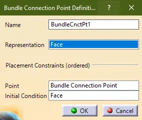
- Finally, the bundle connection point is defined using the "define bundle connection point" option.
Q1: PROTECTION COVERINGS - COT TUBES
Objective :
The objective of this project is to create the cot tubes model and add the models inside the COT TUBE catalog.
Procedure :
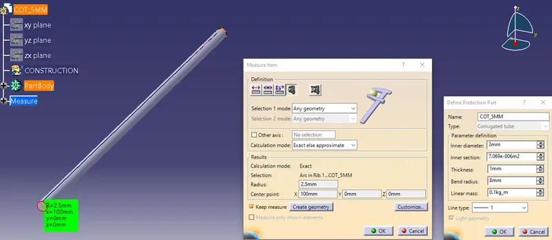
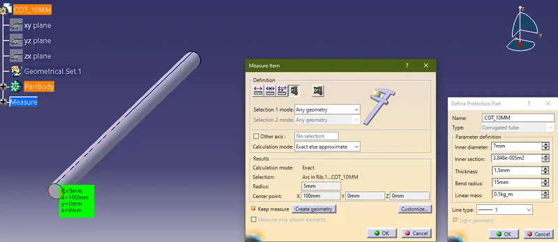
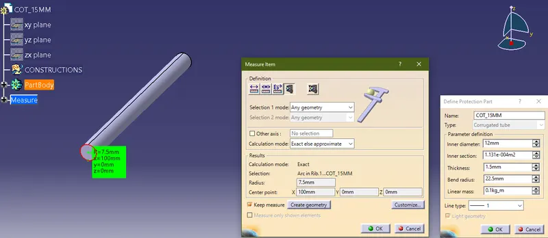
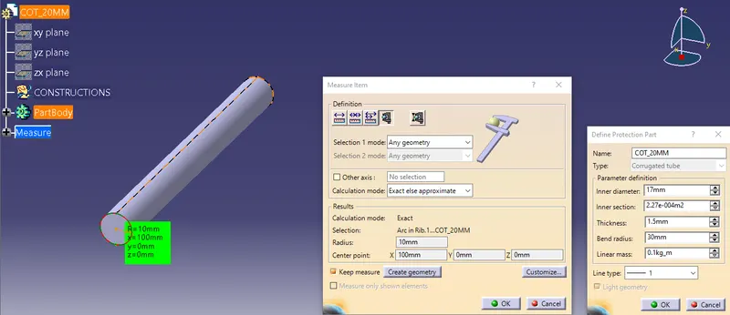
- Initially, the covering part is created by using the "Define Protection Point" in the electrical part design workbench.
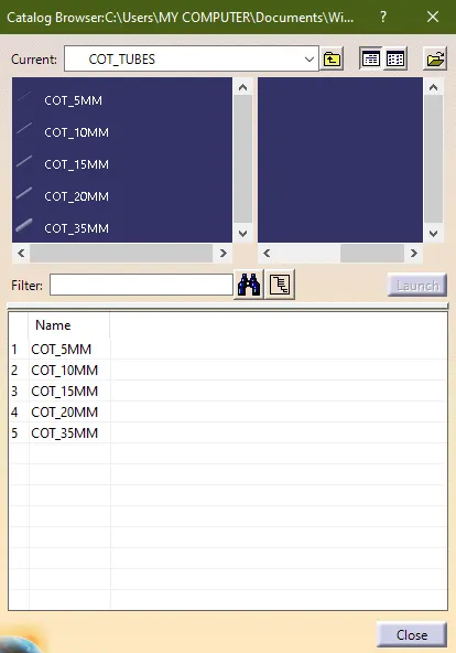
- Then the catalog for the Cot tubes is created.
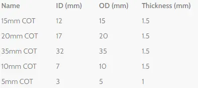
- There are multiple sizes of the COT Tubes are designed as per the below-given table.
5MM
10MM
15MM
20MM
35MM
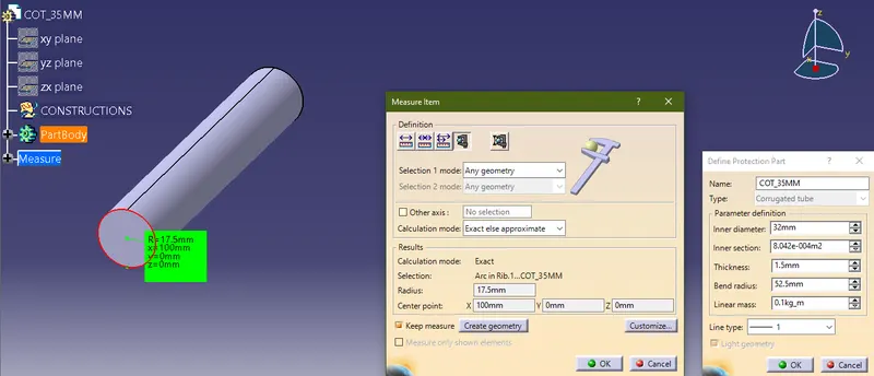
- The create COT tubes are added inside the catalog to use while creating the Harness assembly.