Wiring harness design in CATIA V5 - 3D modeling Week 2 Challlenge
Objective :
The objective of this project is to Convert the mechanical part as an electrical connector and apply the electrical properties to the Connectors.
Procedure :
- Initially, the mechanical model of the required connectors is downloaded.
- After that, the downloaded source file (Stp/Igs) is converted into CAT Part.
- Connector Definition :
1) Create/Download Connector 3D
2) Create required Geometrical Parameters
- In the third step the required reference points like Bundling entry point, Connector connection point, and Cavity connection point.
- Also, the required axis system for the Connector and Cavity is created.
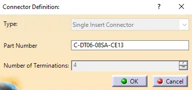
3) Define part as Connector
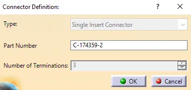
- The parts are defined as connectors by using the "define connector" option in CATIA
- While defining the connector, depending on the connector number of the terminal are mentioned.
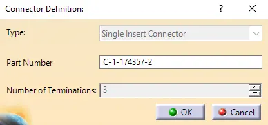
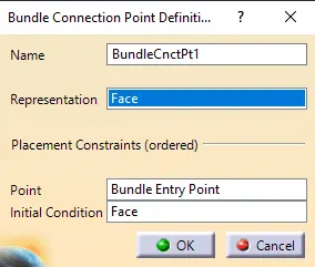
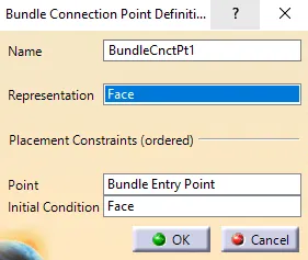
4) Define “Bundle connection point”
- The following parameters are defined for the "Bundle Connection Point"
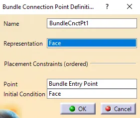
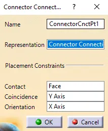
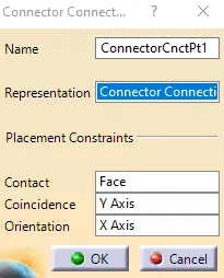
5) Define “ connector connection point”
- The following parameters are defined for the "connector connection point"
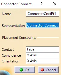
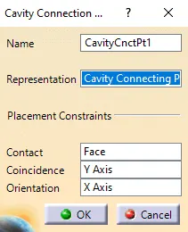
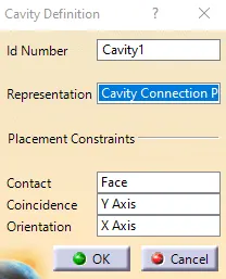
6) Define “ cavity connection point ”
- The following parameters are defined for the "cavity connection point"
- The cavity connection point is an optional one. For some components, we will use a cavity depending on the requirement.
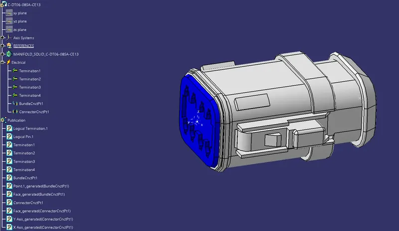
Results :
CONNECTOR_C-DT06-08SA-CE13
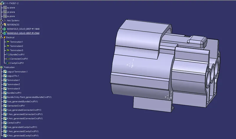
CONNECTOR_C-1-174357-2
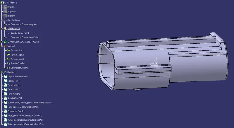
CONNECTOR_C-174359-2
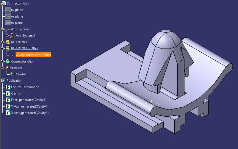
Connector Clip
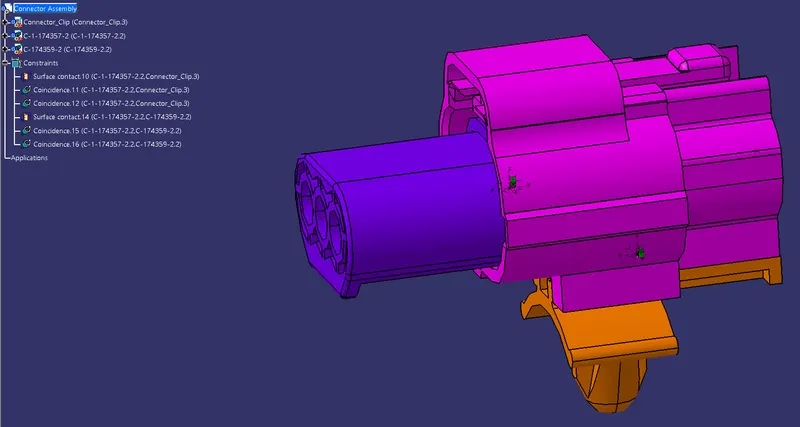
Connector Assembly